Content
- Introduction
- Preparations
- About the Joystick Module
- Examples
Introduction
Joystick is an input device consisting of a stick that pivots on a base and reports its angle or direction to the device it is controlling, and usually have one or more push-buttons whose state can also be read by the computer.
In this lesson, we will learn how Joystick Module works and how to use it to work with the Osoyoo UNO board.
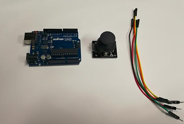
Preparations
Hardware
- Osoyoo UNO Board (Fully compatible with Arduino UNO rev.3) x 1
- Joystick Module x 1
- Breadboard x 1
- Jumpers
- USB Cable x 1
- PC x 1
Software
- Arduino IDE (version 1.6.4+)
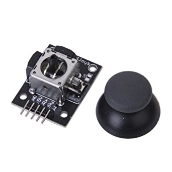
About Joystick Module
What is RTC DS3231?
The Analog Joystick is similar to two potentiometers connected together, one for the vertical movement (Y-axis) and other for the horizontal movement (X-axis). The joystick also comes with a Select switch. It can be very handy for retro gaming, robot control or RC cars.
Specifications
- Directional movements are simply two potentiometers – one for each axis
- Compatible with Arduino interface
- The biaxial XY Joystick Module applies Arduino
- Dimensions: 1.57 in x 1.02 in x 1.26 in (4.0 cm x 2.6 cm x 3.2 cm)
- 5 Pin
- Color: Black
Joystick Pin Outs
The module has 5 pins: +5V, GND, VRx, VRy, SW. Note that the labels on yours may be slightly different, depending on where you got the module from. The thumbstick is analog and should provide more accurate readings than simple ‘directional’ joysticks tat use some forms of buttons, or mechanical switches. Additionally, you can press the joystick down (rather hard on mine) to activate a ‘press to select’ push-button.
- +5V: connect this to your positive supply (usually 5V or 3.3V)
- VRy: this is the vertical output voltage (will be half of VCC when the joystick is centered)
- VRx: this is the horizontal output voltage (will be half of VCC when the joystick is centered)
- SW: this is the output from the pushbutton, normally open, will connect to GND when the button is pushed (see example code below)
- GND: connect this to your ground line (GND)
Note that the pushbutton (SW) is connected to GND when pressed, and open (disconnected) when unpressed. Use a pullup resistor on your digital input so that when it’s unpressed, your input will read 1 (HIGH), and when pressed, the input will read 0 (LOW). Many microcontrollers have internal pullup resistors you can use for this purpose.
Schematic Diagram
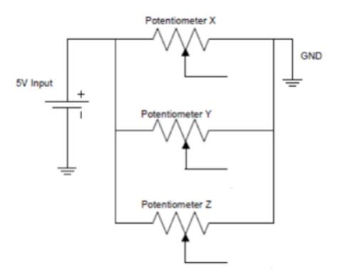
How Does it Work?
This module produces an output of around 2.5V from X and Y when it is in resting position. Moving the joystick will cause the output to vary from 0v to 5V depending on its direction. If you connect this module to a microcontroller, you can expect to read a value of around 512 in its resting position (expect small variations due to tiny imprecisions of the springs and mechanism) When you move the joystick you should see the values change from 0 to 1023 depending on its position.
Examples
Arduino Test Joystick
At the first, we will show how to use the Arduino to test the Joystick module. Here’s an example Arduino sketch which sets up the microcontroller to read the inputs, and then continuously prints the values to the serial monitor.
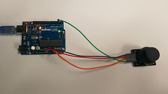
Connection
The wiring between the Joystick Module and the Osoyoo Uno board:
|
Joystick Module
|
Osoyoo Uno
|
|
GND
|
GND
|
|
VCC
|
5V
|
|
VRx
|
A0
|
|
VRy
|
A1
|
|
SW
|
D2
|
Build the circuit as below:

Code Program
After above operations are completed, connect the Arduino board to your computer using the USB cable. The green power LED (labelled PWR) should go on.Open the Arduino IDE and choose corresponding board type and port type for you project. Then load up the following sketch onto your Arduino.
const int xPin = A0; //X attach to A0
const int yPin = A1; //Y attach to A1
const int swPin = 2; //Bt attach to digital 8
void setup()
{
  pinMode(swPin,INPUT); //set btpin as INPUT
  digitalWrite(swPin, HIGH); //and HIGH
  Serial.begin(9600); //initialize serial monitor
}
void loop()
{
  Serial.print("X: "); //print "X: "
  Serial.print(analogRead(xPin),DEC); //read the value of A0 and print it in decimal
  Serial.print("|Y: "); //print "|Y: "
  Serial.print(analogRead(yPin),DEC); //read the value of A1 and print it in decimal
  Serial.print("|Z: "); //print "|Z: "
  Serial.println(digitalRead(swPin)); //read the value of pin8 and print it
  delay(500); //delay 500ms
}
Running Result
A few seconds after the upload finishes, push the joystick and the coordinates of X and Y axis displayed on the Serial Monitor will change accordingly; press down the joystick, and the coordinate of Z=0 will also be displayed.