About NodeMCU
NodeMCU is a very popular Micro controller with wifi access. It is based on ESP8266 – a cheap but powerful chip and fully support Arduino IDE. If you familiar with Arduino IDE, you can program NodeMCU in no time.
Objective:
In this project, we will connect a step motor to a NodeMCU chip, then use a MQTT client(mobile app, browser, linux terminal program etc) to send signal to NodeMCU to control the motor rolling. When MQTT client send message “1” , Step motor will make clockwise rolling. When MQTT client send “0”, motor will make counter-clockwise rolling.
A ULN2003 motor drive module will connected between NodeMCU and step motor. You can read more information about ULN2003 in :https://osoyoo.com/wp-content/uploads/2016/12/ULN2003datasheet.pdf
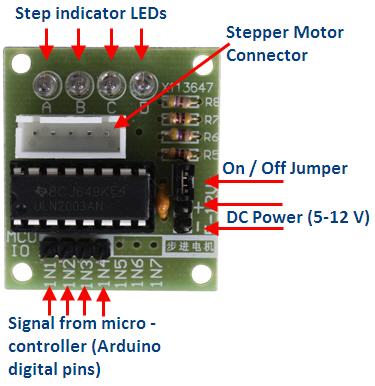
Connection Graph of Step Motor and ULN2003 chip:
Parts and Devices
NodeMCU board x 1 pc
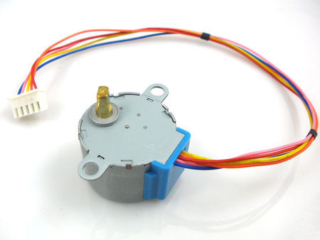
stepper motor+bridge x 1 pc
jumper wires
Circuit Connection Graph between ULN2003 and NodeMCU
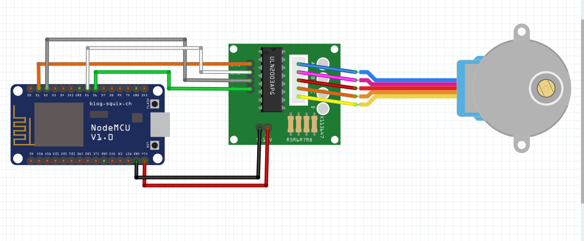
Note: It is highly recommend to provide separate 5V power to ULN2003 chip and the power supply should have same Ground as NODEMCU.
If you don’t have 5V power input , you can use VLN pin as substitution.
Programming Prerequisite:
Before running the project, we need set up the Arduino IDE as per following procedures:
Library Installation:
In Arduino IDE, we need install MQTT client library to communicate with MQTT broker, please download the library from following link: https://osoyoo.com/wp-content/uploads/samplecode/pubsubclient.zip
If you don’t have Arduino Step motor library, please download from https://osoyoo.com/wp-content/uploads/2016/12/Stepper.rar
Unzip above files, move the unzipped folder to Arduino IDE library folder (you can also import these two zip files to Arduino library from IDE).
Download sample code from following link
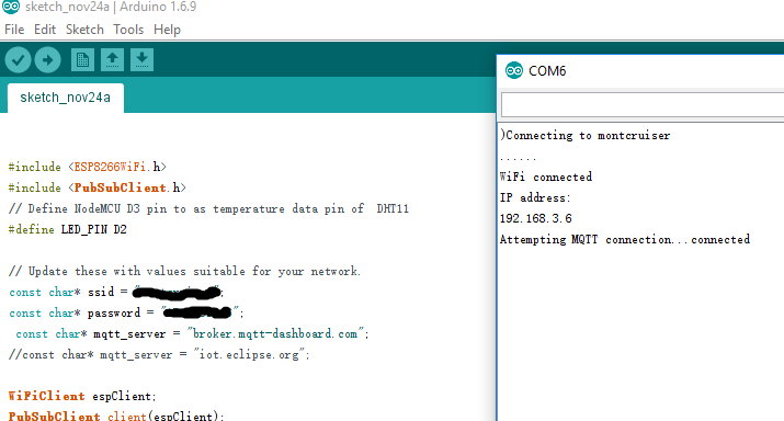
https://osoyoo.com/wp-content/uploads/2016/12/nodemcu_stepper_motor.txt , copy the code into Arduino IDE. Before running the code, please do following changes to fit your wifi and MQTT setting:
1)Line 19 and 20:
const char* ssid = “your_hotspot_ssid”;
const char* password = “your_hotspot_password”;
You need change these 2 lines to match your wifi SSID and password
2)Line 21
const char* mqtt_server = “broker.emqx.io”;
You can use your own MQTT broker URL or IP address to set above mqtt_server value. You can also use some famous free MQTT server to test the project such as “broker.emqx.io”, “iot.eclipse.org” etc
If you want to install your own MQTT broker in Ubuntu Linux, please read this article https://osoyoo.com/2016/09/07/how-to-install-mosquitto-mqtt-server-on-linux
3)if your MQTT server require username and password authentication, you need change line 86
Running the code
After you running the code, please open the serial terminal window in upright corner of Arduino IDE.
If wifi hotspot name and password setting is ok and MQTT broker is connected, you will see following result:
After the NodeMCU connected to wifi and MQTT broker, it will subscribe to a MQTT broker with topic “OsoyooCommand” and waiting for motor control message. Let us publish a message from a MQTT client and test if NodeMCU can get this message.
You can select any MQTT client tool to send control message to MQTT broker(in this project, message must be under topic of “OsyooCommand”). simply use google to search MQTT client in internet, or search MQTT in Apple store or Google Play, you can find many free MQTT client software. In my case, I uses MQTTBox for Windows, you can learn MQTTBox configuration in following article: https://osoyoo.com/2016/12/02/nodemcu-potentiometer-mqtt/
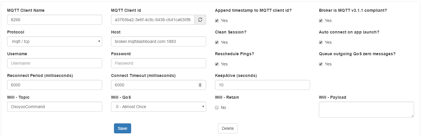
After click Save button, enter into Topic to publish screen,do configuration as following picture:
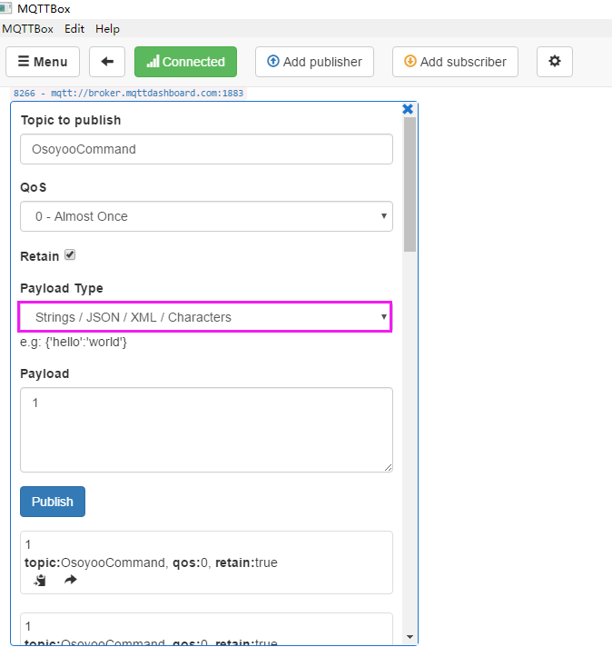
Make sure the topic your NodeMCU code client.subscribe(“OsoyooCommand”) fuction mush match MQTTBOX Topic to publish value
After you publish a “0” or “1” message from payload text field, you step motor will roll as per your instruction.


Hi,
thanks for the great tutorial.
Unfortunately, i have a problem regarding the number of steps per revolution.
I have the same motor as described in the tutorial, but it has 512 steps per revolution.
When I change the value to an amount higher than 256 it stops working….
Do you have an idea whats wrong?
Thanks a lot,
Christian
You may need to add a external power supply for the motor
I’m having an issue that it only spins in the clockwise direction.
I’m also having the same issue as @ck1409 mentions above, anything higher than 200 for me stops it spinning..
Would you be able to tell me which exact model (even a link of where to buy it from) of the nodemcu board you have. I have a feeling mine is slightly different and may be causing some issues…
Thanks!!
you can try to change Pin 9 with Pin 10 to solve only spins in the clockwise direction.
You may need to add a external power supply for the motor for high steps per revolution
Hi, nice tutorial.
Have a some motor as picture, but got some problem. It’s setup per 200 step per rev, but when i try, it make only 20-30 degree rotation, Try to setup motor with higher steps count, but it’s don’t work.
ps. I also modify script, to take direction and count of steps from MQTT payload.
Hello,neykov,
Can you show me the code? I need more details about your project,
you can contact me by [email protected]
Cheers!
David