Authorized Online Retailers:
Introduction
The Raspberry Pi is a credit card-sized minicomputer with a pre-installed Linux system. As for ports, the Raspberry Pi provides ports for mouse and keyboard. In addition, there are also ports for SD card and HDMI display or TV’s connection. Being low cost and low consumption, the Raspberry Pi is very suitable to do very complicated embedded projects through its powerful GPIO pins.
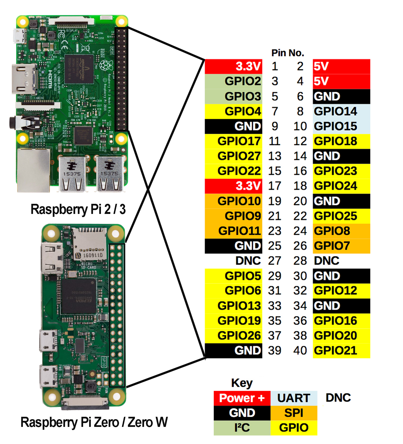
GPIO (General-purpose input/output) are hardware pins rows which locate in the top of RPi board. Raspberry Pi use GPIO pins to interact with other hardware including sensors, motors, and many many other peripheral devices.
Through this kit, you will learn how to use the GPIOs to make simple experiments and how to program GPIO.
The Raspberry Pi evolves through many versions including the latest (so far) Raspberry Pi Zero W, Pi 3 Model B, Pi 2 model B, Pi 1 Model B+, Pi Zero, and Pi 1 Model A+. Different version might different GPIO layout.
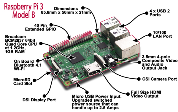
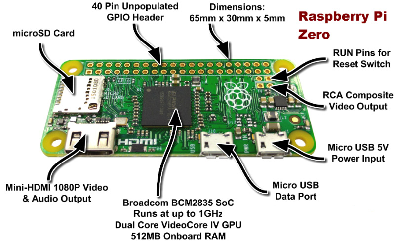
In this tutorial, our default Pi board is Raspberry Pi 3 Model B which supports Bluetooth and Wi-Fi. You can choose according to actual needs. The following is a photo for RPI3 Model B and Pi Zero:
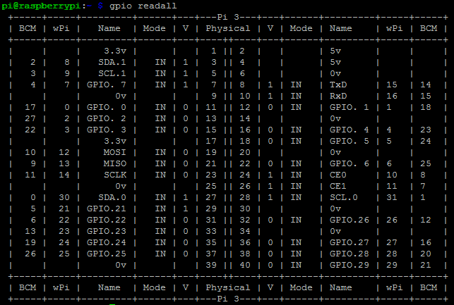
GPIO Pin Name System BCM/Wiringpi and their relation with physical pin location:
There are no pins printed on the latest Raspberry Pi, which may cause difficulties for beginners.
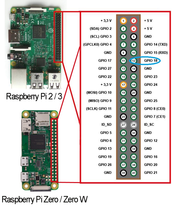
To make thing worse, there are actually three major GPIO naming systems: Physical Pin System, BCM system and WiringPi(WPI) System . WPI is often used in C language and the other two systems are often used in Python. Same physical pin with different number has confused many novice learners. So let’s start to figure it out.
- Raspberry Official Website use BCM system as their default GPIO naming system.
First, let’s talk about Physical Pin number and BCM pin number relationship
In following graph, the number in the circle is the Physical pin number , the word beside the pin is the official name of the GPIO pin.The number followed after GPIO is the BCM number. For example, The Official name of the Physical Pin#12 (in blue circle of following picture) is “GPIO 18”. This means the Physical Pin#12 = BCM Pin#18
How to program BCM and Physical Pin number in Python?
If you use Python to program BCM pin number , the Python code should be like following:
import RPi.GPIO as GPIO
GPIO.setmode(GPIO.BCM)
LedPin = 18
GPIO.output(LEDPIN,GPIO.HIGH)
GPIO.output(LedPin,True)
......
If you want to use Physical Pin number system in Python, Above code must be changed as following:
import RPi.GPIO as GPIO
GPIO.setmode(GPIO.BOARD)
LedPin = 12
GPIO.output(LEDPIN,GPIO.HIGH)
GPIO.output(LedPin,True)
......
Both codes are 100% equal which turns on the LED on Physical Pin 12.
wiringPi(wPi) GPIO Naming system:
wiringPi library is often used in C programming. wiringPi(wPi) number is quite different from that of BCM(Raspberry official naming system).
For example Physical pin#12 is BCM Pin#18 , while in wPi system, it is Pin#1. In order to turn on LED in Physical Pin 12, the C program will be as following:
#include < wiringPi.h>
#define LedPin 1
pinMode(LedPin, OUTPUT);
digitalWrite(LedPin,LOW);
......
By running console command gpio readall, you can get wiringPi name,number and its relations to BCM and Physical Pin system:
Enlarged BCM pin map relation with Physical pin location No.

- GPIO are your standard pins that simply be used to turn devices on and off. For example, a LED.
- I2C (Inter-Integrated Circuit) pins allow you to connect and talk to hardware modules that support this protocol (I2C Protocol). This will typically take up 2 pins.
- SPI (Serial Peripheral Interface Bus) pins can be used to connect and talk to SPI devices. Pretty much the same as I2C but makes use of a different protocol.
- UART (Universal asynchronous receiver/transmitter) are the serial pins used to communicate with other devices.
- DNC stands for do not connect, this is pretty self-explanatory.
- The power pins pull power directly from the Raspberry Pi.
- GND are the pins you use to ground your devices. It doesn’t matter which pin you use as they are all connected to the same line.
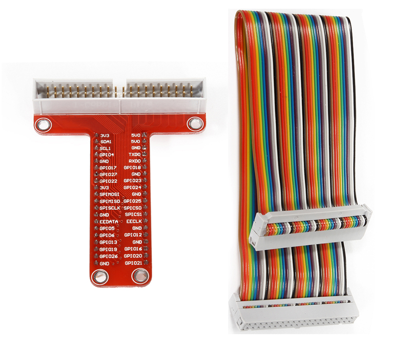
T Type 40-pin GPIO Extension Board
The function of the extension board is to lead out pins of the Raspberry Pi to breadboard by GPIO Extension Board to avoid GPIO damage caused by frequent plugging in or out. For plugging convenience,the kit includes T-Shape GPIO Extension Board with 40 GPIO flat cable
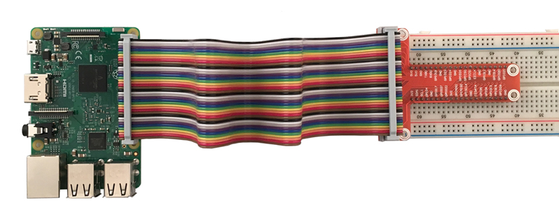
This 40-pin GPIO Extension Board and GPIO cable can be plugged into Raspberry Pi 2 model B and 3 model B. as per following graph :
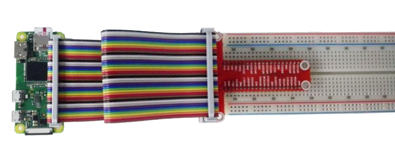
This 40-pin GPIO Extension Board and GPIO cable can be plugged into Raspberry Pi Zero and Zero W. as per following graph :
For your better understanding of every pins, we have drawn a table for you to understand relation between the Name printed in T board , BCM# and wiringPi#