Note: ALL OSOYOO Products for Arduino are Third Party Board which is fully compatitable with Arduino
Authorized Online Retailers:
Content
- Introduction
- Preparations
- About this project
- Connection
- Upload Sketch
- Program Running Result
Introduction
In this lesson, we will show how to use the 74HC595 to drive a single 7-segment LED display on the Osoyoo basic board. We’ve already shown how to connect the single 7-segment LED display directly to eight ports on the board. By this way, we can save five ports – considering the board’s limited ports, this is very important.
Preparations
Hardware
- Osoyoo basic Board (Fully compatible with Arduino UNO rev.3) x 1
- One Digit 7-Segment LED Display x 1
- 74HC595 x 1
- 200 ohm Resistor x 8
- Breadboard x 1
- Jumpers
- USB Cable x 1
- PC x 1
Software
- Arduino IDE (version 1.6.4+)
About this project
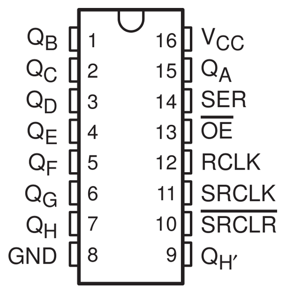
In the experiment SRCLR (pin10) is connected to 5V (HIGH Level) and OE (pin 13) to GND (LOW Level). Therefore, the data is input into the rising edge of SRCLK and enters the memory register through the rising edge. We use the shiftout() function to output a 8-bit data to the shift register through DS. In the rising edge of the SRCLK, the data in the shift register moves successively one bit in one time, i.e. data in QB moves to QC, and so forth. In the rising edge of RCLK, data in the shift register moves into the memory register. All data will be moved to the memory register after 8 times. Then the data in the memory register is output to the bus (QA-QH). So the 16 characters are displayed in the 7-segment in turn.
Connection
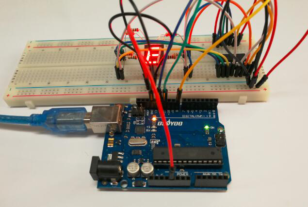
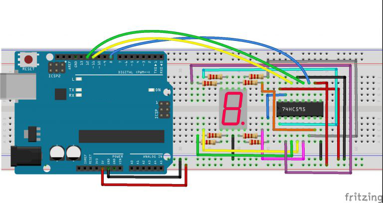
Build the circuit as below:
Upload Sketch
After above operations are completed, connect the board to your computer using the USB cable. The green power LED (labelled PWR) should go on. Load up the following sketch onto your Osoyoo basic board.
const int latchPin = 12;//Pin connected to latchPin of 74HC595
const int clockPin = 8;//Pin connected to clockPin of 74HC595
const int dataPin = 11; //Pin connected to dataPin of 74HC595
//display 0,1,2,3,4,5,6,7,8,9,A,b,C,d,E,F
int datArray[16] = {252, 96, 218, 242, 102, 182, 190, 224, 254, 246, 238, 62, 156, 122, 158, 142};

void setup ()
{
  //set pins to output
  pinMode(latchPin,OUTPUT);
  pinMode(clockPin,OUTPUT);
  pinMode(dataPin,OUTPUT);
}
void loop()
{
  //loop from 0 to 256
  for(int num = 0; num < 16; num++)
  {
    digitalWrite(latchPin,LOW); //ground latchPin and hold low for as long as you are transmitting
    shiftOut(dataPin,clockPin,MSBFIRST,datArray[num]);
    //return the latch pin high to signal chip that it
    //no longer needataPin to listen for information
    digitalWrite(latchPin,HIGH); //pull the latchPin clockPin to save the data
    delay(1000); //wait for a second
  }
}
Running Result
A few seconds after the upload finishes, you should now see the 7-segment display from 0 to 9 and A to F.


