Note: ALL OSOYOO Products for Arduino are Third Party Board which is fully compatitable with Arduino
Content
- Introduction
- Preparations
- About the IR Obstacle Avoidance Sensor
- Example
- Connection
- Upload Sketch
- Program Running Result
Introduction
Infrared IR Sensor Obstacle Avoidance Sensor board is an inexpensive solution to avoidance detection for robotics , smart car and other electronics uses. In this lesson we will show you how the Obstacle Avoidance Sensor works and how to use it with the Osoyoo Uno board.
Preparations
Hardware
- Osoyoo UNO Board (Fully compatible with Arduino UNO rev.3) x 1
- Obstacle Avoidance Sensor x 1
- Breadboard x 1
- Jumpers
- USB Cable x 1
- PC x 1
Software
- Arduino IDE (version 1.6.4+)
About Obstacle Avoidance Sensor

Infrared Obstacle Sensor Module has builtin IR transmitter and IR receiver that sends out IR energy and looks for reflected IR energy to detect presence of any obstacle in front of the sensor module. The module has on board potentiometer that lets user adjust detection range. The sensor has very good and stable response even in ambient light or in complete darkness.
The Obstacle Avoidance Sensors usually come in two types – with 3 and 4 pins. The 3 pin version does not have the ability to be enabled/disabled. The 4 pin version has optional Enable pin. Here I am describing the 4 pin version that I have. The information should also be relevant to other versions of the sensor.
Specification
- Working Voltage: DC 3.3V-5V
- Working Current: ≥20mA
- Working Temperature: -10℃—+50℃
- Detection Distance: 2-40cm
- IO Interface: 4 wire interface (-/+/S/EN)
- Output Signal: TTL voltage
- Accommodation Mode: Multi-circle resistance regulation
- Effective Angle: 35°
- Size: 41.7*16.7mm
- Weight: 5g
Working Principle
The IR transmitter sends an infrared signal that, in case of a reflecting surface (e.g. white color), bounces off in some directions including that of the IR receiver that captures the signal detecting the object.
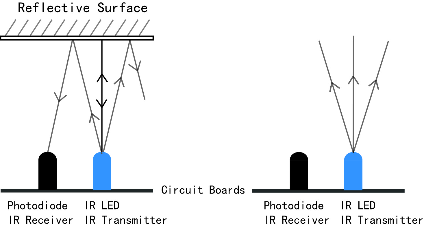
When the surface is absorbent (e.g. black color) the IR signal isn’t reflected and the object cannot be detected by the sensor. This result would occur even if the object is absent.
How it Works ?
At the heart of the sensor is an NE555 chip configured to generate a 38kHz square wave. The 38kHz signal is used to illuminate an Infra Red (IR) LED. Light reflected from the LED is detected by a IR receiver module. The receiver module incorporates an external, optical, 950nm IR filter and an internal, electronic, 38kHz band-pass filter that make the module receptive only to IR light pulsing at that frequency.
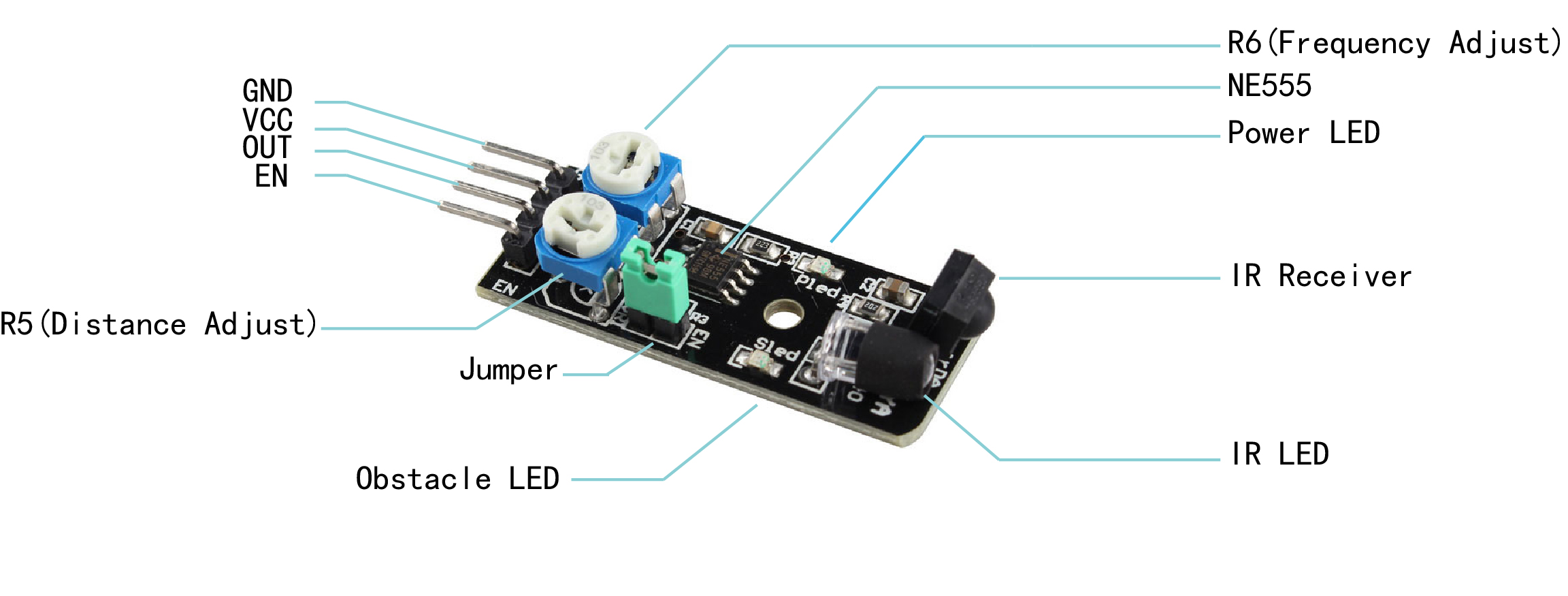
The Infrared Obstacle Avoidance Sensor has Power, Ground, Signal, and Enable pins.
There are also 2 potentiometers, and one jumper on the board (See the Picture).
The potentiometer R5 on the picture is used to adjust how sensitive the sensor is. You can use it to adjust the distance from the object at which the sensor detects it.
The potentiometer R6 on the picture usually should not be changed. It controls the frequency of the infrared signal, and is preset with a good setting. You may need to use it if there is infrared interference with other infrared sources, but otherwise, avoid changing it.
The receiver module also includes an AGC (Automatic Gain Control) that will suppress a continuous signal of any frequency, including 38kHz. Therefore, it is absolutley necessary to use the ‘EN’ or ‘Enable’ pin for proper operation of the device. If the Enable function is used correctly, the device will achieve its maximum sensitivity.
On some versions of this device, the Infra Red (IR) LED is already covered with a small piece of black shrink tubing; but I find that additional optical shielding is required.
When the JUMPER is installed on the board, the IR LED will flicker continuously at 38kHz. If the Enable (EN) function will not be used, the jumper must be installed . When the jumper is removed, pin 4 of the 555 timer is held LOW (RESET) by R3, a 22K pull-down resistor. Then, if a HIGH condition is applied to the EN pin, the reset condition will be relieved and the 555 timer will begin to oscillate. The Enable function cannot be used if the JUMPER is in place. You must remove the jumper on the board in order to use the EN (Enable) pin.
Examples
Using the Obstacle Avoidance Sensor with OSOYOO Basic board
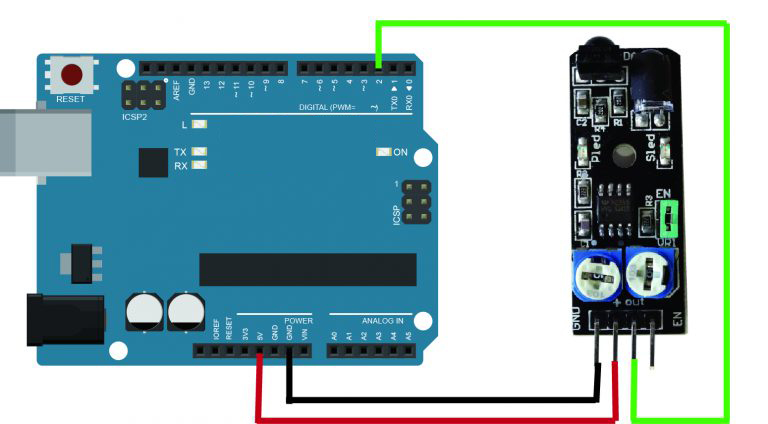
In this experiment, we will use an Obstacle Avoidance Sensor module and the LED attached to pin 13 of the Osoyoo Uno board to build a simple circuit. Since the LED has been attached to pin 13, connect the pin OUT to digital pin 2 of the Uno board. When the Obstacle Avoidance Sensor detects an obstacle, the LED will be on. Otherwise it will be off.
Note: The detection distance of the infrared sensor is adjustable – you may adjust it by the potentiometer.
Connection
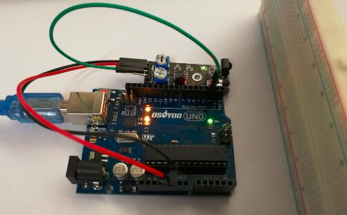
Make sure the Enable Jumper is placed on the Infrared Obstacle Avoidance sensor, Build the circuit as below digram:
Code Program
After above operations are completed, connect the board to your computer using the USB cable. The green power LED (labelled PWR) should go on.Open the Arduino IDE and choose corresponding board type and port type for you project. Then load up the following sketch onto your board.
int LED = 13; // Use the onboard Uno LED
int isObstaclePin = 2;  // This is our input pin
int isObstacle = HIGH;  // HIGH MEANS NO OBSTACLE

void setup() {
  pinMode(LED, OUTPUT);
  pinMode(isObstaclePin, INPUT);
  Serial.begin(9600);
}

void loop() {
  isObstacle = digitalRead(isObstaclePin);
  if (isObstacle == LOW)
  {
    Serial.println("OBSTACLE!!, OBSTACLE!!");
    digitalWrite(LED, HIGH);
  }
  else
  {
    Serial.println("clear");
    digitalWrite(LED, LOW);
  }
  delay(200);
}
Running Result
A few seconds after the upload finishes, place a board in front of the Obstacle Avoidance Sensor, and the LED attached to pin 13 on the Osoyoo Uno board will light up, the on-board obstacle led will turn on. It will turn off when there is no obstacle.
At the same time, choose the corresponding port type for you board and open the Serial Monitor of the Arduino IDE, make sure the baudrate is same as your code, move the obstacle in front of the Obstacle Avoidance Sensor, you will see the serial output as below: