Introduction
In this project, we will show how to drive a single 7 segment LED display with an Osoyoo Uno board.
Preparations
HARDWARE
- Osoyoo UNO Board (Fully compatible with Arduino UNO rev.3) x 1
- One digit 7-Segment LED Display x 1
- 200 ohm Resistor x 8
- Breadboard x 1
- Jumpers
- USB Cable x 1
- PC x 1
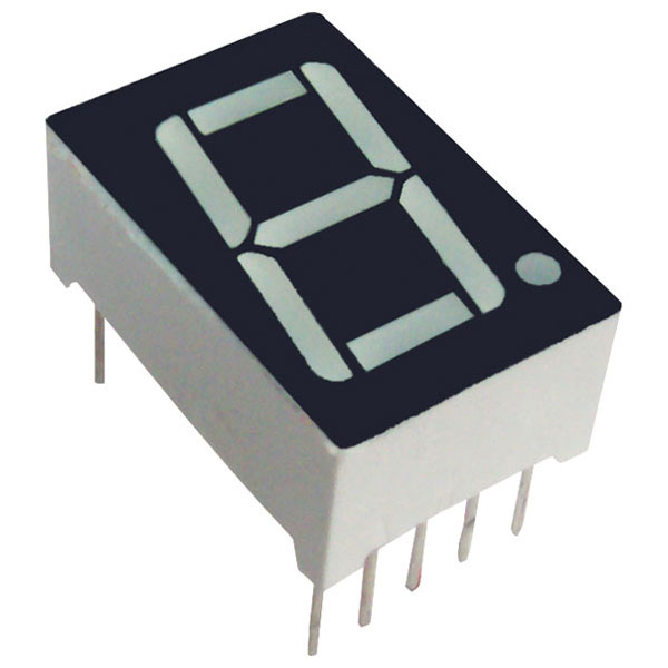
About the 1 Digit 7 Segment LED Display
One digit seven segment displays are used in many embedded system and industrial applications where the range of outputs to be shown is known beforehand. Basic 1 digit seven segment display can show numbers from 0-9 and a few characters. 7 segment displays are of different types; especially they differ in the number of digits/character it can display. Basically a 7 segment display is a single unit, which can display only 1 digit or 1 character. More digits are displayed by multiplexing single unit 7 segment displays together to form 2 digit display, 3 digit display or 4 digit 7 segment display. Its quiet easy to interface Arduino and 7 Segment display together! Lets begin the tutorial.
A 7 segment display has many limitations, especially in the range of characters it can display.There are displays in market which are much more advanced than seven segment displays and can display almost every character in the alphabet. For example:- a 16×2 LCD – which can display almost all ASCII characters. You might think why 7 segment display still exist in market. Well, 7 segment displays are the cheapest option when it comes to display devices available in market. A single digit/character 7 segment display unit is available at 1/10th of the cost of a 16×2 LCD module.
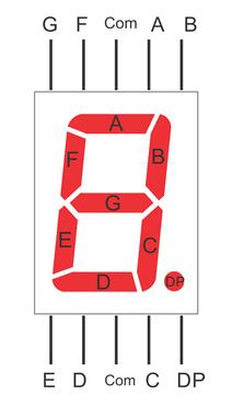
Each of the LEDs in the display is given a positional segment with one of its connection pins led out from the rectangular plastic package. These LED pins are labeled from “a” through to “g” representing each individual LED. The other LED pins are connected together forming a common pin. So by forward biasing the appropriate pins of the LED segments in a particular order, some segments will brighten and others stay dim, thus showing the corresponding character on the display.
The common pin of the display generally tells its type. There are two types of pin connection: a pin of connected cathodes and one of connected anodes, indicating Common Cathode (CC) and Common Anode (CA). As the name suggests, a CC display has all the cathodes of the 7 LEDs connected when a CA display has all the anodes of the 7 segments connected.
Common Cathode 7-Segment Display
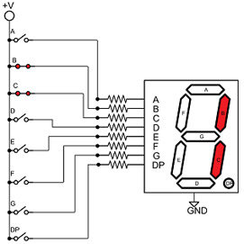
In a common cathode display, the cathodes of all the LED segments are connected to the logic “0” or ground. Then an individual segment (a-g) is energized by a “HIGH”, or logic “1” signal via a current limiting resistor to forward bias the anode of the segment.
As shown in the following figure, the segment pins b and c set to “HIGH”.
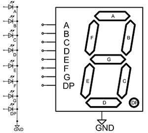
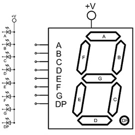
Common Anode 7-Segment Display
In a common anode display, the anodes of all the LED segments are connected to the logic “1”. Then an individual segment (a-g) is energized by a ground, logic “0” or “LOW” signal via a current limiting resistor to the cathode of the segment.
As shown in the following figure, the segment pins b and c set to “LOW”.

Note:
Even though many different types of 7 segment LED displays follow the above schematics, it is not guaranteed. The best way to know the connections is to obtain the datasheet for the LED display in use or to buzz it out by connecting power to each of the pins to see which lights up. If you don’t get the connections right, the circuit will not produce the output of showing numerals 0-9. So it is very important to know which pins are which.
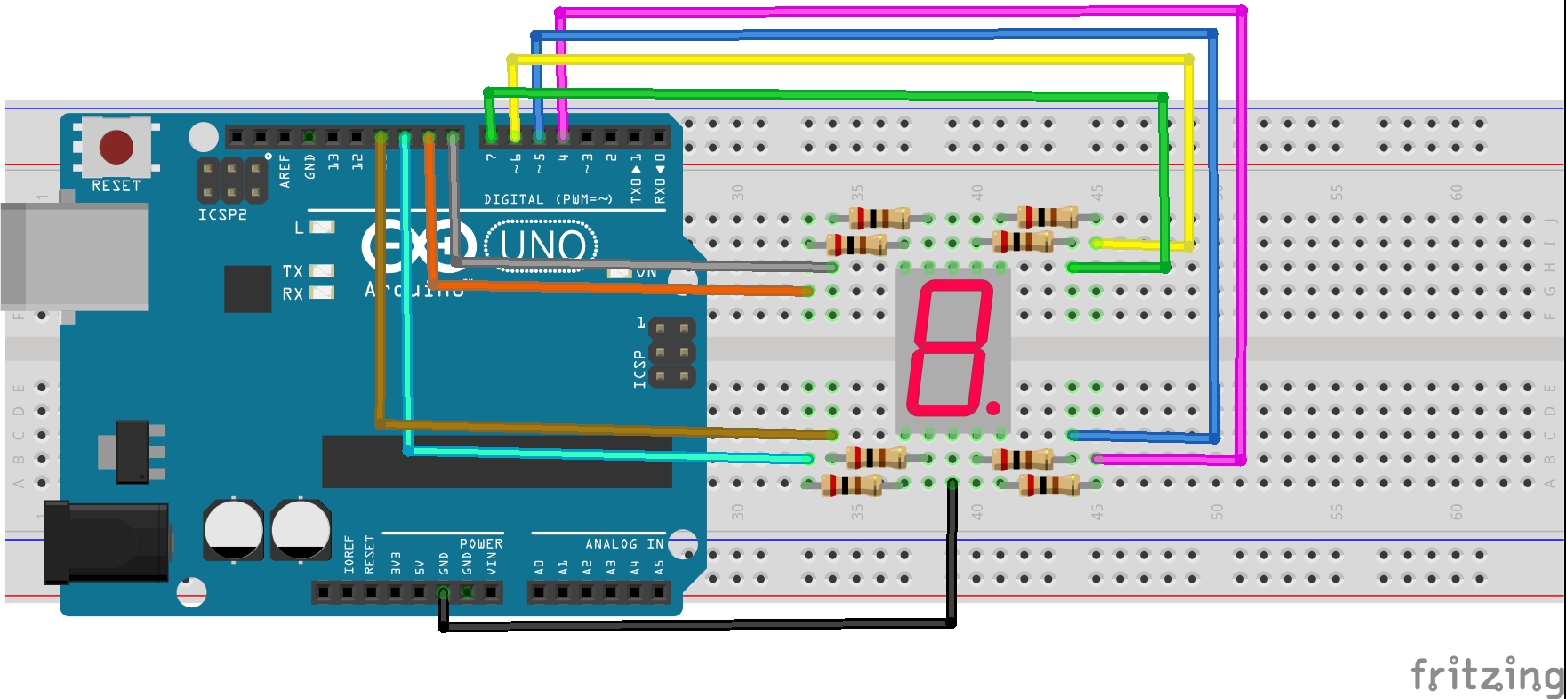
Connection
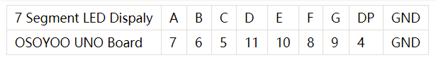
In this experiment, connect each of pin A-G of the 7-Segment Display to one 200 ohm current limiting resistor respectively and then to pin 4–11. GND connects to GND. By programming, we can set one or several of pin4-11 as High level to light up the corresponding LED(s).
The wiring between the 7-segment display and the SunFounder Uno board:
|
7-Segment Display
|
Osoyoo Uno Board
|
|
A
|
7
|
|
B
|
6
|
|
C
|
5
|
|
D
|
11
|
|
E
|
10
|
|
F
|
8
|
|
G
|
9
|
|
DP
|
4
|
|
Com
|
GND
|
Circuit Diagram
CODE PROGRAM
After above operations are completed, connect the Arduino board to your computer using the USB cable. The green power LED (labelled PWR) should go on. Open the Graphical Programming software Mixly and follow the next operations:
Note: The code will be a little long You’re recommended to open the sample code file to check.
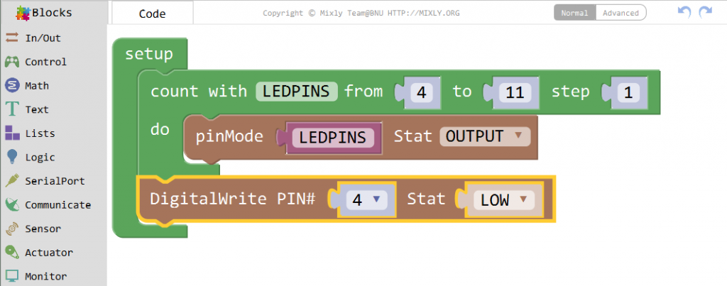
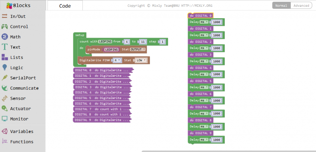
Connect each pin of the 7-segment Display to pin 4-11, and set as OUTPUT. No need to light up the DP if the display is only used to show number or string, thus here set pin 4 LOW.
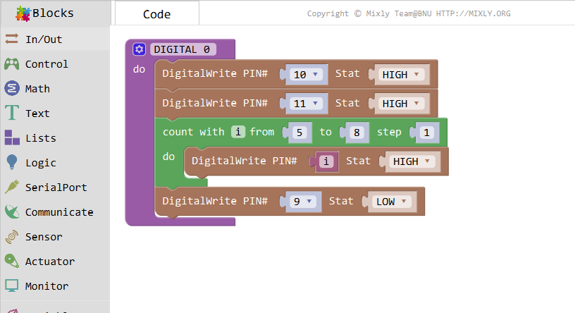
Drag out a function and name it DIGITAL 0 to display number 0, that is, to light up the corresponding segments of the number 0, and dim the others.
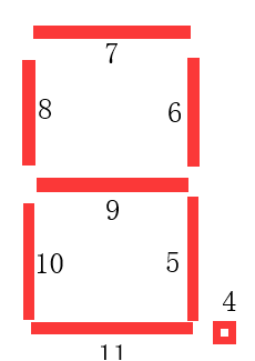
First we need to know how it looks like when display the number 0 on the 7-segment display It’sactually the segments A, B, C, D, E and F are power on, which generates the display of 0. In programming, pins connected to these segments are set High level when G is Low level. We can know pin G is connected to pin 9 as shown below, so we set pin 9 to Low, and other pins to High. No need to light up DP, so dp(pin4) has been set to LOW in setup.
After running this part, the 7-segment will display.
Note:
Actually, the display of other characters is the same. Since the letters b and d in upper case, namely B and D, would look the same with 8 and 0 on the display, they are displayed in lower case instead.
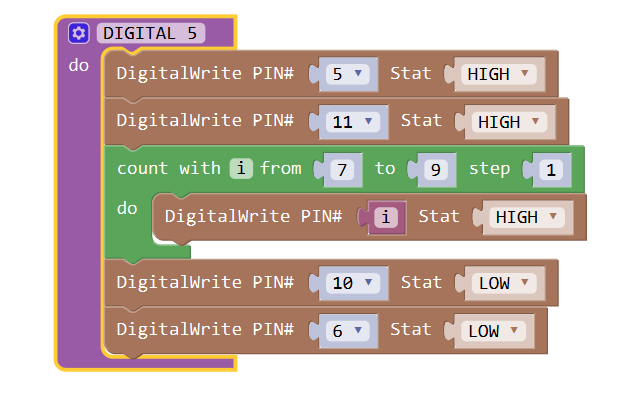
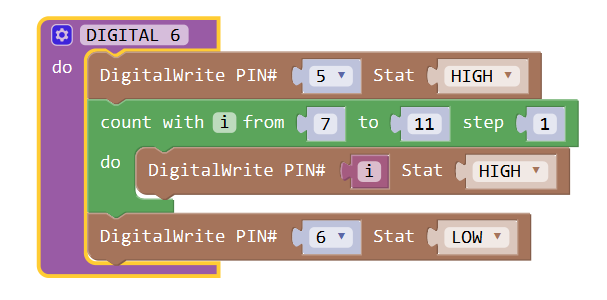
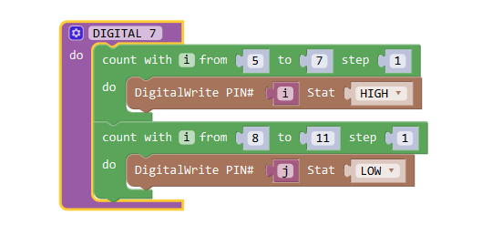
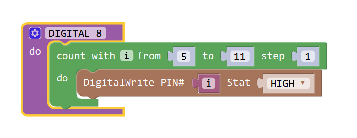
You can see code of the digital 1 to digital 9 as below:
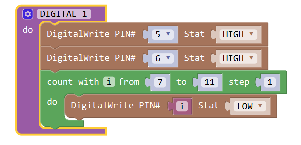
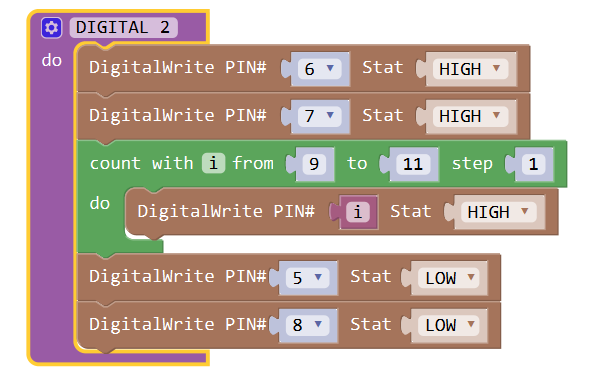
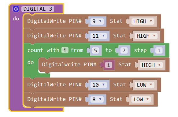


The code is a bit long, Collapse Block as follows:

Then set loop function for these numbers, and set a delay for 1000ms each time.

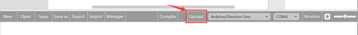
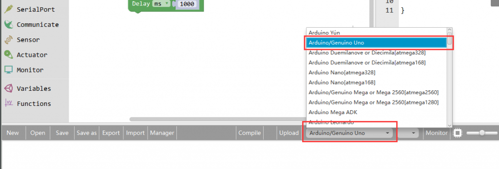
Click Save aftogramming is done. Select the board type and serial port before uploading. For instause a Uno board, just select Arduino/Genuino Uno: if you use a Mega2560, select Arduino/Genuino Mega or Mega2560.
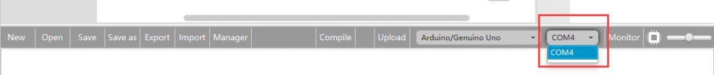
Select the serial device of the Arduino board from the COM menu. This is likely to be COM3 or higher (COM1 and COM2 are usually reserved for hardware serial ports). To find out, you can disconnect your Arduino board and re-open the menu; the entry that disappears should be the Arduino board. Reconnect the board and select that serial port.
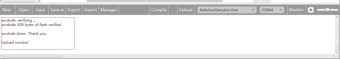
Next,upload the code. If the uploading fails, check and correct the code according to the prompts

Finally, the staus will change to ‘Upload success!’.

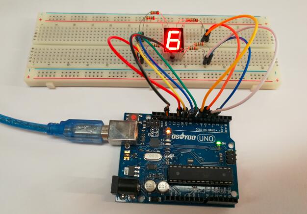
Running Result
A few seconds after the upload finishes, you should now see the 7-segment display from 0 to 9.