Product: OSOYOO ESP32 Motor Driver Board v1.0
MCU module: Espressif ESP32-WROOM-32E (Wi-Fi 802.11 b/g/n + Bluetooth 4.2 / BLE)
Motor driver: L293DD dual H-bridge, 2 channels (K1&K2 and K3&K4 paralleled)
Programming: USB Type-C (onboard CH340 USB-to-serial, auto-download)
1Product Introduction
The OSOYOO ESP32 Motor Driver Board v1.0 is a compact, all-in-one robot-car control and IoT development board built around the Espressif ESP32-WROOM-32E module. On a single 70 × 54 mm PCB it combines a powerful Wi-Fi + Bluetooth MCU, an L293DD dual H-bridge motor driver, an onboard CH340 USB-to-serial interface, regulated power supplies, and a full set of plug-and-play sensor connectors.
The ESP32-WROOM-32E module handles all logic, GPIO control, and 2.4 GHz Wi-Fi / Bluetooth wireless communication, while the integrated L293DD H-bridge drives the wheel motors directly. A Type-C USB port with the onboard CH340 lets you program the ESP32 straight from the Arduino IDE, ESP-IDF, or MicroPython, with an auto-download circuit so no manual button pressing is needed during upload.
Around the core, the board breaks out everything a smart car or IoT node needs: four motor connectors (K1&K2 and K3&K4 paralleled into two groups), a 5-channel line-tracking header, an ultrasonic header, an IR header, a servo header, an I²C header for an MPU6050 motion sensor, a buzzer, status LEDs, and spare 3.3 V / 5 V / VIN power pins and GPIO breakouts. A wide-range battery input (VIN 7–18 V) plus onboard 5 V and 3.3 V regulators let the board run a complete robot from a single battery pack. A “Motor Power” jumper switches motor-module power on or off for safe bench testing.
2Target Application Areas
2.1 Robot Cars & Motion Control
- 2WD / 4WD smart cars: drive left/right motor groups with independent speed and direction (PWM).
- Line-following robots: use the 5-channel IR tracking header to follow a track.
- Obstacle-avoidance / following cars: combine the ultrasonic header and IR sensor for collision avoidance or object/hand following.
- Self-balancing / heading-hold robots: add an MPU6050 for gyro and accelerometer feedback.
- Pan/tilt & gripper mechanisms: drive an SG90-class servo from the servo header.
2.2 IoT & Wireless Applications
- Wi-Fi / Bluetooth app-controlled cars: drive the robot from a phone app.
- Remote monitoring / telemetry: stream speed, voltage, and distance data to a dashboard or cloud.
- MQTT / web-server projects: the ESP32 can host a web UI or publish to an MQTT broker.
- Smart-home & automation nodes: use the spare GPIO / I²C pins for relays, displays, or sensors.
- STEM & classroom teaching: one board covers motors, sensors, and wireless lessons.
3Features
- All-in-one design: MCU, motor driver, USB-serial, and power supply on one board — no separate driver shield or USB adapter required.
- ESP32-WROOM-32E: dual-core 240 MHz processor with 2.4 GHz Wi-Fi and Bluetooth / BLE, 4 MB flash.
- L293DD dual H-bridge: two motor channels with PWM speed control; K1&K2 and K3&K4 are paralleled into two groups (up to two DC motors each).
- Plug-and-play USB-C: onboard CH340 USB-to-serial with auto-reset/download; program directly from the Arduino IDE.
- “Motor Power” jumper : a 2-pin header whose jumper cap switches the motor-module VM supply on/off — remove it to cut motor power and program/debug safely without the motors running.
- Rich sensor interfaces: dedicated headers for 5-channel line tracking, ultrasonic ranging, IR, servo, and an MPU6050.
- Onboard buzzer (GPIO12) for audible feedback.
- Wide battery input: VIN 7–18 V with reverse-polarity protection and onboard 5 V / 3.3 V regulators.
- Broken-out power pins: spare 3.3 V, 5 V, VIN, and GND pins for powering external modules (output capability in Section 6).
- Power switch & status LEDs: ON/OFF slide switch; Power / RX / TX LEDs; BOOT & RESET buttons.
4Specifications
4.1 MCU Module – ESP32-WROOM-32E
| Parameter |
Specification |
| Module |
Espressif ESP32-WROOM-32E-N4 |
| Processor |
Xtensa dual-core LX6, up to 240 MHz |
| Memory |
520 KB SRAM, 4 MB on-chip flash |
| Wi-Fi |
IEEE 802.11 b/g/n, 2.4 GHz |
| Bluetooth |
Bluetooth v4.2 BR/EDR + BLE |
| Module supply |
3.3 V |
| Antenna / certification |
On-module PCB antenna; FCC / CE / IC certified |
4.2 Motor Driver & Electrical
| Parameter |
Specification |
| Motor driver |
L293DD dual H-bridge |
| Motor channels |
2 channels, PWM speed control; K1&K2 and K3&K4 paralleled into two groups (up to two DC motors each) |
| Output current/channel |
~600 mA continuous / 1.2 A peak (L293DD spec) |
| Motor connectors |
K1–K4, XH2.54 sockets; flyback diode protected |
| USB interface |
USB Type-C, CH340 USB-to-UART with auto-download/reset |
| Logic voltage |
3.3 V |
| Power input |
USB-C 5 V, or battery / VIN 7–18 V DC |
| Onboard regulators |
5 V step-down + 3.3 V regulator; reverse-polarity protection |
| I²C interface |
SDA → GPIO21, SCL → GPIO22 (for MPU6050) |
5Onboard Components
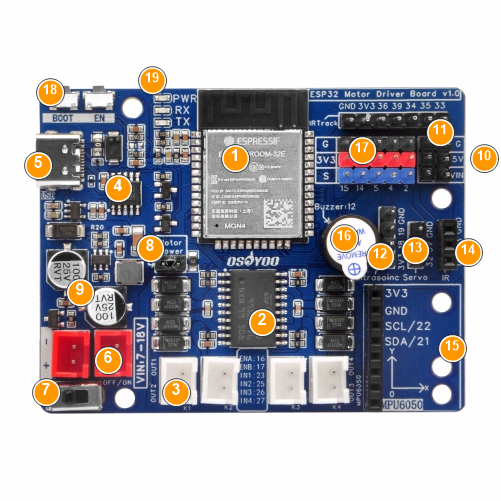 Fig.2 – Board layout (numbers match the component table below)
| No. |
Silkscreen |
Component |
Function |
| ① |
U1 / ESP32-WROOM-32E |
MCU module |
The brain of the board. Dual-core processor with 2.4 GHz Wi-Fi and Bluetooth / BLE; handles all GPIO, PWM, I²C, and wireless tasks. Programmable with the Arduino IDE, ESP-IDF, or MicroPython. |
| ② |
U2 / L293DD |
Motor driver IC |
Dual H-bridge driver controlling motor direction and speed. Speed is set by PWM on the enable pins (ENA/ENB), direction by the input pins (IN1–IN4). |
| ③ |
K1 / K2 / K3 / K4 |
Motor connectors (XH2.54) |
Four 2-pin motor sockets. K1 & K2 are paralleled as Channel A and K3 & K4 as Channel B, forming two independently controlled motor groups, each driving up to two DC motors (ideal for a 4-wheel car with left/right pairs). |
| ④ |
U6 / CH340K |
USB-to-serial IC |
Connected to the USB Type-C port; lets the computer program and serial-debug the ESP32. An auto-reset circuit puts the ESP32 into download mode automatically — no manual buttons during upload. |
| ⑤ |
USB |
USB Type-C port |
Power (5 V) and firmware upload / serial. For logic and light loads only; use VIN battery power to drive motors. |
| ⑥ |
VIN 7-18V |
Battery / power input (XH2.54) |
Accepts 7–18 V DC from a battery or supply. Reverse-polarity protected; feeds the onboard regulators (5 V / 3.3 V) and the motor supply. |
| ⑦ |
OFF / ON |
Power switch |
Slide switch for main board power; lets you cut power without unplugging the battery. |
| ⑧ |
Motor Power |
Motor-supply jumper (2-pin) |
A 2-pin header whose jumper cap switches the motor-module VM supply on/off. With the cap on, VIN feeds the L293DD VM and motors run; remove the cap to cut motor power so you can upload, debug, or test the logic safely without the motors turning. |
| ⑨ |
5 V / 3.3 V regulators |
Onboard step-down supplies |
Convert the 7–18 V VIN input into stable 5 V and 3.3 V rails for servos / 5 V peripherals and for the ESP32 / 3.3 V logic (output capability in Section 6). |
| ⑩ |
3V3 / 5V / VIN / GND |
Power breakout pins |
Spare 3.3 V, 5 V, VIN, and GND pins for powering external sensors, modules, or servos. See the power table in Section 6 for approximate output capability. |
| ⑪ |
IRTrack (GND 3V3 36 39 34 35 33) |
5-ch line-tracking header |
Connects a 5-channel IR tracking sensor array; the five signals map to GPIO36 / 39 / 34 / 35 / 33 (all input-only), plus 3.3 V and GND. |
| ⑫ |
Ultrasoinc |
Ultrasonic header |
For an HC-SR04-style distance sensor: Trig → GPIO18, Echo → GPIO19, plus power and GND. |
| ⑬ |
Servo |
Servo header |
S / V / G 3-pin header, signal on GPIO32, 5 V power; drives an SG90-class RC servo (pan/tilt, gripper, etc.). |
| ⑭ |
IR |
IR header |
For an IR receiver / obstacle-avoidance module; signal on GPIO13, plus 3.3 V and GND. |
| ⑮ |
MPU6050 / SCL 22 · SDA 21 |
I²C / MPU6050 header |
2.54 mm header for an MPU6050 6-axis motion sensor or other I²C devices. SDA → GPIO21, SCL → GPIO22, plus 3.3 V and GND. |
| ⑯ |
Buzzer-12 |
Onboard buzzer |
Active buzzer driven by GPIO12 for tones and alerts. |
| ⑰ |
Breakout (IO2/4/5/14/15) |
GPIO breakout pins |
Spare GPIO2 / 4 / 5 / 14 / 15 broken out with 3.3 V and GND for custom expansion. |
| ⑱ |
BOOT / EN |
BOOT & RESET buttons |
BOOT (GPIO0) enters firmware download mode; EN is reset. Normal uploads are handled automatically by the auto-download circuit. |
| ⑲ |
PWR / RX / TX |
Status LEDs |
PWR = power indicator; RX (GPIO3) / TX (GPIO1) = serial activity — quick check of power and communication. |
 Fig.3 – Circuit schematic
6Power & Supply
The board can be powered from USB-C (5 V) or the VIN battery input (7–18 V). After reverse-polarity protection, VIN feeds the onboard step-down regulators that produce the 5 V and 3.3 V rails, and supplies the L293DD motor module through the “Motor Power” jumper. The table below lists the broken-out power pins and their approximate output capability.
| Pin |
Source |
Voltage |
Approx. current |
Notes |
| VIN |
Battery input (passthrough) |
≈ input (7–18 V) |
Limited by battery & board traces/protection — typically a few amps |
Tapped directly from the VIN input for higher-power external modules; voltage follows the battery. |
| 5V |
Onboard 5 V step-down |
5 V |
Up to ~3 A total (shared with servos & onboard 5 V loads) |
Powers servos and 5 V sensors/modules; leave headroom — keep external draw ≤ ~1.5 A continuous. |
| 3.3V |
Onboard 3.3 V regulator |
3.3 V |
≤ ~500 mA recommended for external loads |
This rail also powers the ESP32 and onboard logic; intended for 3.3 V sensors, not high-current loads. |
| GND |
Common ground |
0 V |
— |
Always share a common ground with any external module. |
Note: The currents above are approximate references; actual capability depends on input voltage, ambient temperature, and cooling. When stacking multiple loads, budget the total power to avoid overloading or overheating the regulators.
⚠ Debug tip: When uploading firmware or testing logic alone, pull off the “Motor Power” jumper cap to cut motor power and prevent the motors from spinning unexpectedly; refit the cap afterward to restore motor drive.
7GPIO / Pin Map
Default ESP32 GPIO assignments (silkscreen) for the onboard functions:
| Function |
ESP32 GPIO |
| Motor Channel A – Enable / PWM (ENA) |
GPIO16 |
| Motor Channel B – Enable / PWM (ENB) |
GPIO17 |
| Motor input IN1 / IN2 |
GPIO23 / GPIO25 |
| Motor input IN3 / IN4 |
GPIO26 / GPIO27 |
| Buzzer |
GPIO12 |
| Servo signal |
GPIO32 |
| IR receiver |
GPIO13 |
| Ultrasonic Trig / Echo |
GPIO18 / GPIO19 |
| Line tracking (5 ch) |
GPIO33 / 34 / 35 / 36 / 39 |
| I²C SDA / SCL (MPU6050) |
GPIO21 / GPIO22 |
| UART RX / TX LEDs |
GPIO3 / GPIO1 |
| BOOT button |
GPIO0 |
| Spare GPIO breakout |
GPIO2 / 4 / 5 / 14 / 15 |
Note: GPIO34–39 are input-only with no internal pull-ups — ideal for sensor inputs such as line tracking. GPIO0 (BOOT) is a strapping pin; avoid pulling it low at power-on.
8Mechanical Information
 Fig.4 – PCB 3D render
| Parameter |
Specification |
| PCB size |
70.0 mm × 54.0 mm |
| PCB thickness |
1.6 mm |
| Mounting holes |
4 ×, for M3 standoffs |
| Motor / power connectors |
XH2.54 sockets |
| Sensor / servo headers |
2.54 mm pitch |
| USB connector |
USB Type-C (edge) |
9Related Documents
| Document |
Description |
Link |
| ESP32 Motor Driver Board schematic |
Circuit schematic for this product, v1.0 (PDF) |
Included with product files |
| Robot car tutorials & sample code |
osoyoo.com ESPro Robot Drive Board lessons (line tracking, obstacle avoidance, Wi-Fi / Bluetooth control, etc.) |
osoyoo.com |
| ESP32-WROOM-32E datasheet |
Espressif module datasheet (electrical specs, pinout, RF characteristics) |
Download |
| Arduino-ESP32 core |
ESP32 Arduino core install & usage docs (boards manager URL included) |
Online docs |
10Cautions & Notes
Warning: Switch the power OFF before plugging or unplugging motors, sensors, or the battery. Hot-plugging under power can damage the board or peripherals.
1. Battery voltage range
Keep the VIN battery input within 7–18 V. Do not exceed the rated input, and observe correct polarity on the battery connector (reverse-polarity protection is provided, but wire it correctly anyway).
2. Do not power motors from USB alone
USB-C 5 V is for programming / logic only. Use VIN battery power to drive motors under load, and make sure the “Motor Power” jumper cap is fitted.
3. Motor current limits
The L293DD suits small DC gear motors (~600 mA per channel). Avoid stalling high-current motors for long periods to prevent overheating. Paralleling K1&K2 / K3&K4 increases per-group current capacity.
4. Power-pin load capability
The 3.3 V pin also powers the ESP32 — keep external loads ≤ ~500 mA; the 5 V pin shares the step-down output with servos, so leave headroom. Budget total power and cooling when stacking loads.
5. Input-only & strapping pins
GPIO34–39 cannot be outputs and have no internal pull-ups — use them as sensor inputs only. GPIO0 (BOOT) is a strapping pin; avoid pulling it low at power-on so the board boots normally.
6. Common ground
Always share a common ground with any external sensor, servo, or module, otherwise signals may be unstable or fail to work.