Note: ALL OSOYOO Products for Arduino are Third Party Board which is fully compatitable with Arduino
Overview
In this lesson, we will learn how to control a servo motor with a remote control. This will give you a general concept on how to control remotely. You should know that the remote control sends Infrared (IR) signals, so we will learn how to receive and read these signals using board compatible with Arduino.
Preparations
Hardware
- Osoyoo Basic Board (Fully compatible with Arduino UNO rev.3) x 1
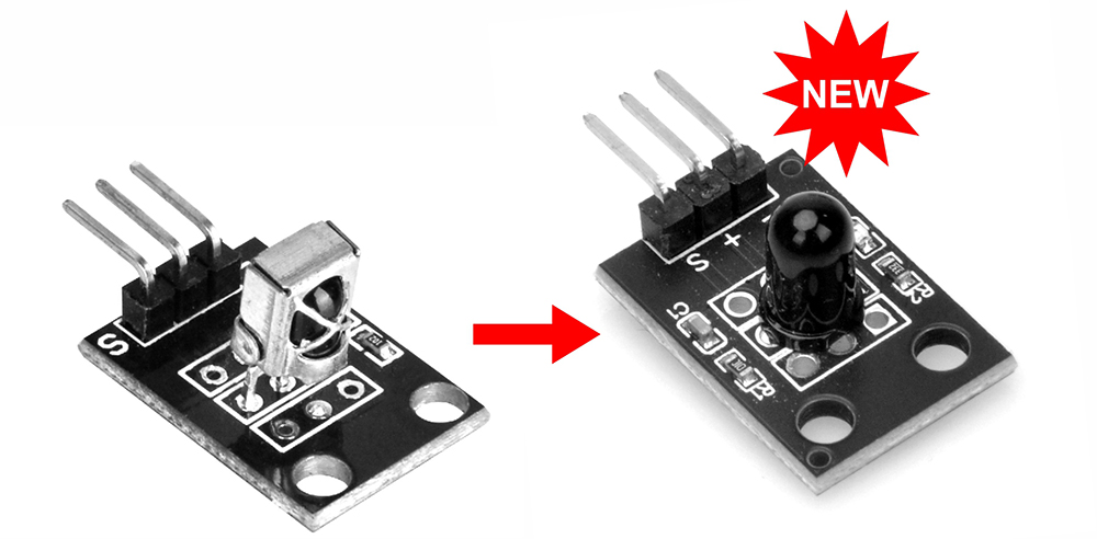
- Infrared Receiver x 1
- Remote Controller x 1
- SG90 Servo x 1
- Jumpers
- USB Cable x 1
- PC x 1
Software
Examples
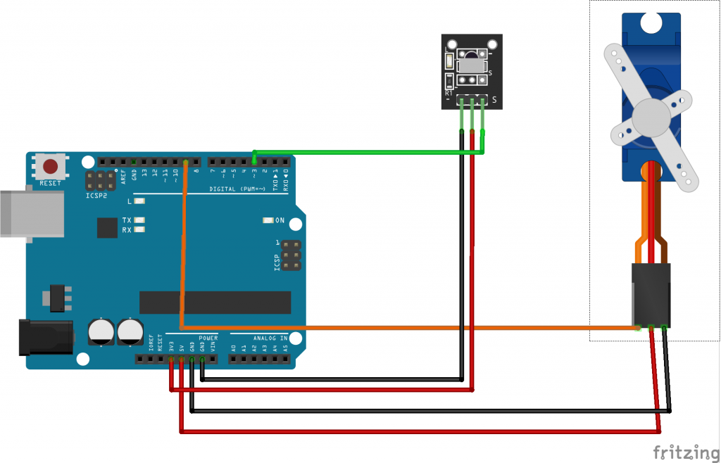
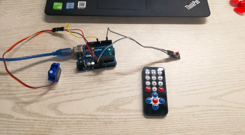
We use OSOYOO Basic Board to control the servo motor and give us the functionality we want. We use the IR receiver to read IR signals from the remote control. The wiring for the IR receiver and servo motor are shown in pictures. Follow the steps for wiring in the pictures.
Use the IRremote Library to Control a Servo
First, download the IR remote library for Arduino from here: IR library
Open this IRremote example , then upload it to the board.
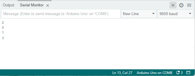
The sketch will automatically decode the type of remote you are using and identify which button on your remote is pressed. Open the Serial Monitor in the Arduino IDE at 9600 bps and hit different buttons on your remote.
Now press each key on the remote control and record the corresponding value you see in the serial monitor.
Then detect the command of the buttons used to control the servo motor; assume you will use two buttons of your choice, one for clockwise rotation and another for counter clockwise rotation.
For example, use (▲) for clockwise and (▼) for counterclockwise, so you have to get their command values.
Code Program
After above operations are completed, connect the board to your computer using the USB cable. The green power LED (labelled PWR) should go on.Open the IDE and choose corresponding board type and port type for you project. Then load up the following sketch onto your board.
#include “IRremote.hpp” //must copy IRremote library to arduino libraries
#include
#define plus 24 //clockwise rotation button
#define minus 82 //counter clockwise rotation button
#define IR_RECEIVE_PIN 3 //IR receiver Signal pin connect to Arduino pin D3
Servo servo;
int val; //rotation angle
bool cwRotation, ccwRotation; //the states of rotation
void setup()
{
Serial.begin(9600);
IrReceiver.begin(IR_RECEIVE_PIN, DISABLE_LED_FEEDBACK);
servo.attach(9); //servo pin
}
voidloop()
{
if (IrReceiver.decode()) {
uint16_t command = IrReceiver.decodedIRData.command;
IrReceiver.resume();// Receive the next value
if (command == plus)
{
cwRotation = !cwRotation; //toggle the rotation value
ccwRotation = false; //no rotation in this direction
}
if (command == minus)
{
ccwRotation = !ccwRotation; //toggle the rotation value
cwRotation = false; //no rotation in this direction
}
}
if (cwRotation && (val != 175)) {
val++; //for colockwise button
}
if (ccwRotation && (val != 0)) {
val–; //for counter colockwise button
}
servo.write(val);
delay(20); //General speed
}
Running Result
In thisl code, the functionality allows you to click any two buttons for the motor to toggle between adjusting rotation directions and stopping. When you first click one button, the motor will rotate the button’s direction, and when you secondly click the same button the motor will stop.
Use the IRLibAll Library to Control a Servo
In this example we will control the servo using the IRLibAll library. We can adjust the speed that the servo moves and we can select individual preset angles for positioning the servo.
Cconnection
As above fritzing picture we have an IR receiver connected to +3.3v, ground, and pin 3. We also have a servo with three wires. The red wire is +5v. The black or dark brown wire is ground and the remaining wire usually yellow is the signal wire which we have connected to pin 9 although it could be any digital output pin.
Installing the IR Library IRLibAll
To install the IR Library:
- Download the IR Library by clicking the button above, or download it directly from the IRLib 2.x Library from Github.
- Uncompress the ZIP file after it’s finished downloading.
- Check that the uncompressed folder contains five separate folders. IRLib 2.x contains multiple libraries that work together.
- Copy all five into your Library folder root directory. The path will typically be in (home)/Documents/in Arduino folder/Libraries. If you do not see the /Libraries/ folder, you may need to create this yourself.
- Restart the IDE.
Upload the Code
Below is a version of the servo.ino sketch from the “IRLib2/examples” folder. It has been modified to be used with the OSOYOO Smart Car V1 Remote. If you’re using a different remote, you will have to collect information about your codes for various buttons using dump.ino and modify the sketch with the proper protocol name and codes.
#include <IRLibAll.h>
#include <Servo.h>

// You will have to set these values depending on the protocol
// and remote codes that you are using. These are For the Adafruit
// Mini Remote
#define MY_PROTOCOL NEC
#define RIGHT_ARROW   0xFF5AA5 //Move several clockwise
#define LEFT_ARROW    0xFF10EF //Move servo counterclockwise
#define SELECT_BUTTON 0xFF38C7 //Center the servo
#define UP_ARROW      0xFF18E7 //Increased number of degrees servo moves
#define DOWN_ARROW    0xFF4AB5 //Decrease number of degrees servo moves
#define BUTTON_0 0xFF9867  //Pushing buttons 0-9 moves to fixed positions
#define BUTTON_1 0xFFA25D  // each 20 degrees greater
#define BUTTON_2 0xFF629D
#define BUTTON_3 0xFFE21D
#define BUTTON_4 0xFF22DD
#define BUTTON_5 0xFF02FD
#define BUTTON_6 0xFFC23D
#define BUTTON_7 0xFFE01F
#define BUTTON_8 0xFFA857
#define BUTTON_9 0xFF906F

IRrecv myReceiver(2); //pin number for the receiver
IRdecode myDecoder;

Servo myServo;  // create servo object to control a servo
int16_t pos;         // variable to store the servo position
int16_t Speed;       // Number of degrees to move each time a left/right button is pressed
uint32_t Previous;//handles NEC repeat codes

void setup() {
  myServo.attach(9);      // attaches the servo on pin 9 to the servo object
  pos = 90;               // start at midpoint 90 degrees
  Speed = 3;              // servo moves 3 degrees each time left/right is pushed
  myServo.write(pos);     // Set initial position
  myReceiver.enableIRIn(); // Start the receiver
}

void loop()
{
    if (myReceiver.getResults()) {
       myDecoder.decode();
       if(myDecoder.protocolNum==MY_PROTOCOL) {
         if(myDecoder.value==0xFFFFFFFF)
           myDecoder.value=Previous;
         switch(myDecoder.value) {
            case LEFT_ARROW:    pos=min(180,pos+Speed); break;
            case RIGHT_ARROW:   pos=max(0,pos-Speed); break;
            case SELECT_BUTTON: pos=90; break;
            case UP_ARROW:      Speed=min(10, Speed+1); break;
            case DOWN_ARROW:    Speed=max(1, Speed-1); break;
            case BUTTON_0:      pos=0*20; break;
            case BUTTON_1:      pos=1*20; break;
            case BUTTON_2:      pos=2*20; break;
            case BUTTON_3:      pos=3*20; break;
            case BUTTON_4:      pos=4*20; break;
            case BUTTON_5:      pos=5*20; break;
            case BUTTON_6:      pos=6*20; break;
            case BUTTON_7:      pos=7*20; break;
            case BUTTON_8:      pos=8*20; break;
            case BUTTON_9:      pos=9*20; break;
         }
         myServo.write(pos); // tell servo to go to position in variable 'pos'
         Previous=myDecoder.value;
       }
       myReceiver.enableIRIn();
    }
}
Special Instructions for ATmega32u4 based systems
The example as presented here should work okay on OSOYOO Basic board or Mega however if you are using Arduino Leonardo, Arduino Micro, Arduino Yun or other ATmega32u4 based systems, you will have to make a slight modification to IRLib.
IRLib uses your board’s built in hardware timers to generate an interrupt every 50µs so it can poll the input pin to see if it has changed. By default it uses TIMER2. The servo library also uses hardware interrupts using TIMER1. However the ATmega32u4 processor does not have TIMER2 so IRLib defaults to TIMER1 on systems using that processor. You will have to modify “IRLibProtocols/IRLibHardware.h” to change the default timer. In that file at approximately line 56 you will see something like this:
#elif defined(__AVR_ATmega32U4__)
  #ifdef CORE_TEENSY
    // it's Teensy 2.0
    //#define IR_SEND_TIMER1  14
    //#define IR_SEND_TIMER3  9
    #define IR_SEND_TIMER4_HS 10
  #else
  /* it's probably Leonardo */
    #define IR_SEND_TIMER1    9
    //#define IR_SEND_TIMER3  5
    //#define IR_SEND_TIMER4_HS 13
  #endif
You will need to put // in front of #define IR_SEND_TIMER1 to comment out that line. Then remove the slashes from in front of one of the other two options either TIMER3 or TIMER4_HS. Note that these defines say “IR_SEND_TIMERxx”. Later in the file we copy this value to also be used as the receiving timer. If you’re using Leonardo and you later use IRLib to send IR signals you will need to make note of the numbers after these defines. Although we can hook a receiver to any digital input pin, IRLib requires you to use specific output pins depending on which timer you are using. Will cover that later in the section on sending.
Running Result
Upload the sketch and try pushing the left and right arrow buttons. The servo should turn left and right. Pushing the enter button should center the servo. Pushing the up or down arrow buttons will not have any visible effect but it will change the speed of movement you push left or right. The numbered buttons from zero through nine move the servo to 10 different fixed positions at 20° intervals.
If the servo behaves erratically, it may be a power supply problem. Some USB ports do not deliver sufficient current to drive the the board and move the servo. You may need to add an external 5 volt supply.


