


| Buy from US |
Buy from UK |
Buy from DE |
Buy from IT |
Buy from FR |
Buy from ES |
Buy from JP |
 |
 |
 |
 |
 |
 |
 |

In this lesson, we will show how to use OSOYOO Basic Board for Arduino to control an active buzzer module and make beep alarm.

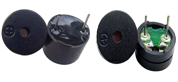
Buzzers, which are supplied by DC power, are widely used in computers, printers, photocopiers, alarms, electronic toys, automotive electronic devices, telephones, timers and other electronic products as sound devices. Buzzers can be categorized as active and passive ones (see the following picture). Turn the pins of two buzzers face up, and the one with a green circuit board is a passive buzzer, while the other enclosed with a black tape is an active one.
The difference between an active buzzer and a passive buzzer is:
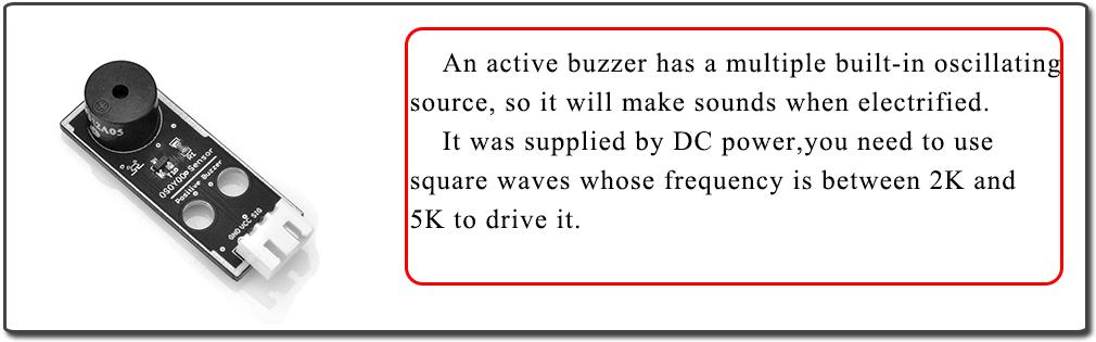
An active buzzer has a built-in oscillating source, so it will make sounds when electrified. But a passive buzzer does not have such source, so it will not beep if DC signals are used; instead, you need to use square waves whose frequency is between 2K and 5K to drive it. The active buzzer is often more expensive than the passive one because of multiple built-in oscillating circuits.
In this lesson, we use an active buzzer.
Note: As the sound frequency is decided by the build-in oscillator circuit, you can not change the frequency of the beep by software.

- OSOYOO Basic Board for Arduino (Fully compatible with Arduino UNO rev.3) x 1
- OSOYOO Magic I/O Shield for Arduino x 1
- OSOYOO Active Buzzer x 1
- OSOYOO 3-Pin PNP Cable x 1
- USB Cable x 1
- PC x 1

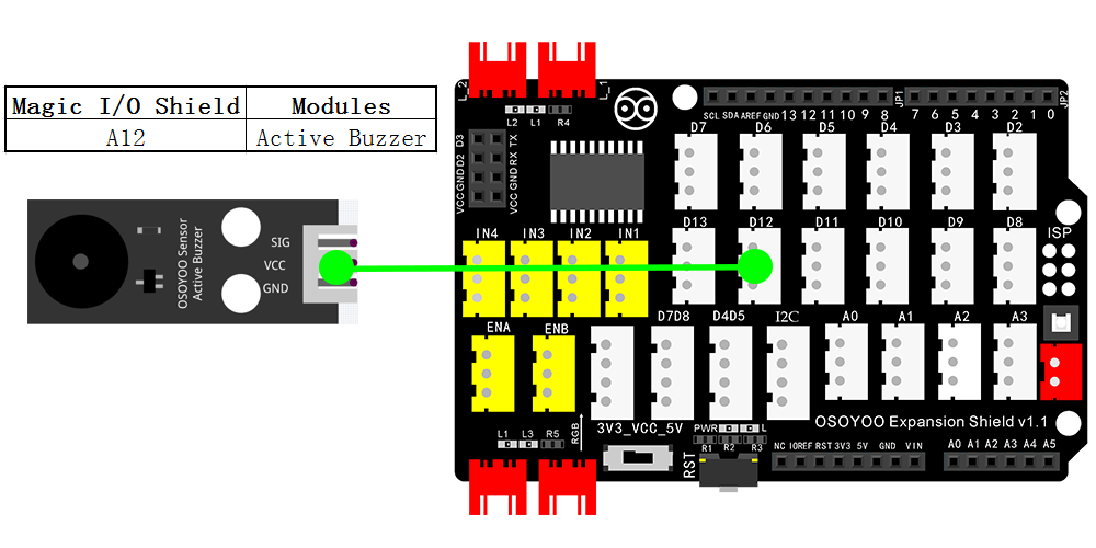
Please plug OSOYOO magic I/O board onto UNO board First. Then connect buzzer module to Port D12 in Osoyoo Magic I/O board with a 3-pin PNP cable. Circuit connection picture as below:

Notice: Shut off your battery or Unplug your power adapter when upload sketch code to OSOYOO Basic Board for Arduino.
You can download the code directly, then click “Open” in Mixly to choose the code you download:
Or you can do as following operations:
After above operations are completed, connect the OSOYOO Basic Board for Arduino to your computer using the USB cable. The green power LED (labelled PWR) should go on.Open the Graphical Programming software Mixly and follow the next operations,this lesson is very similar to the LED lessons.
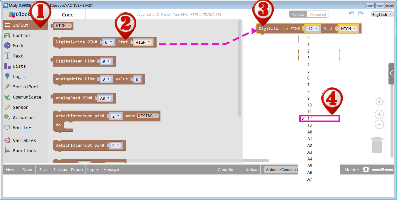
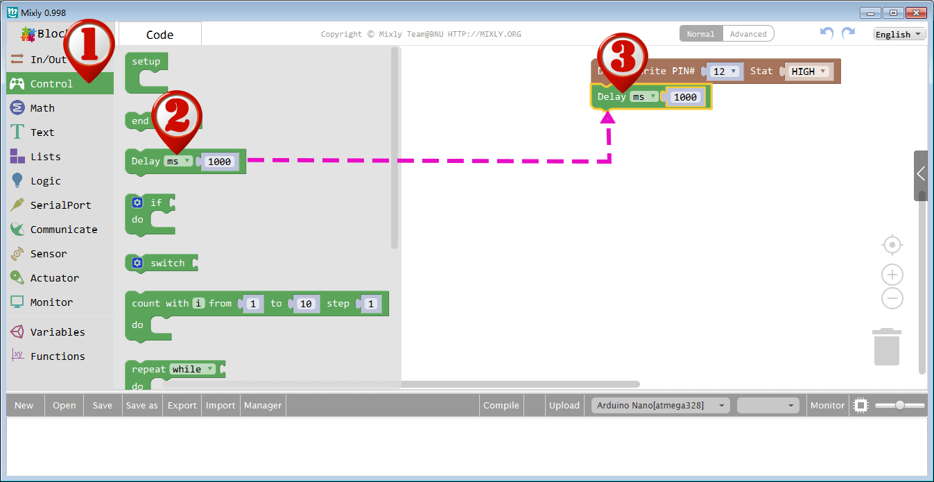
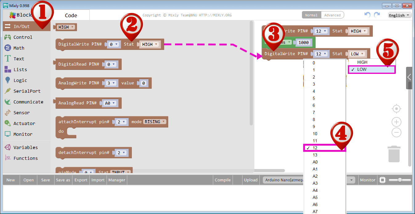
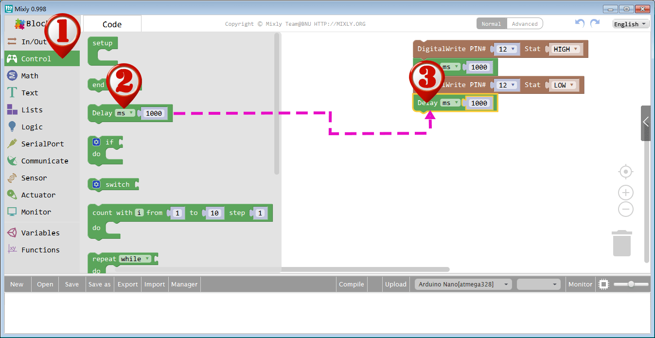
This program will give a high or low level to the buzzer connected pin 12 to turn it on and off. After programming, you can click the “<” button to check the corresponding code on the right bar.
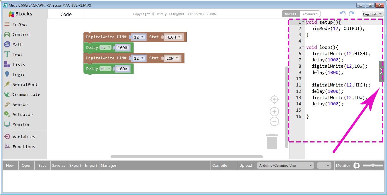
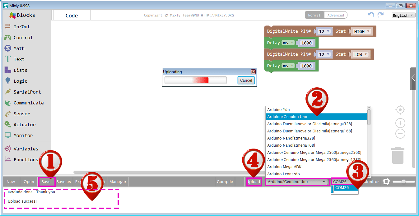
(1)Click Save after programming is done.
(2) Select the board type and serial port before uploading. In our case, we are using Uno board, so just select Arduino/Genuino Uno.
(3) Select the serial device of the OSOYOO Basic Board for Arduino from the COM menu.
(4)Next,upload the code. If the uploading fails, check connection according to the prompts.
(5)Finally, the status will change to ‘Upload success!’.

A few seconds after the upload finishes, you should hear the buzzer beep.
Note again:
The active buzzer has built-in oscillating source, so it will beep as long as it is electrified, but it can only beep with a fixed frequency.


