In this lesson, we will show how to use a Button Switch module to turn on/off an LED through Graphic programming for Arduino technology.
Both LED and Switch module will be connected to OSOYOO Magic I/O shield. Here, “I/O” refers to the INPUT and OUTPUT. OSOYOO Magic I/O Shield is an extension board which can help use to easily connect sensors, actuators and Robot car control ports to OSOYOO Basic Board for Arduino I/O pins.
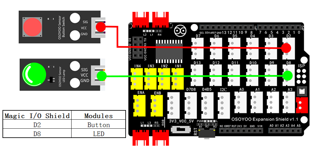
We will plug LED module into D8 port of the shield and plug Switch module to D2 port on the shield. We will tell OSOYOO Basic Board for Arduino D8 will be an OUTPUT port which will send out signal to control LED. D2 is an INPUT port which gets input signal from Switch button.
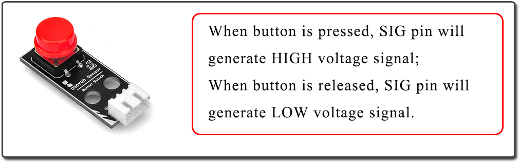
The Button Switch module is signal generator device. When button pressed, SIG pin will generate HIGH voltage signal, when button is released, SIG pin will generate LOW voltage signal.
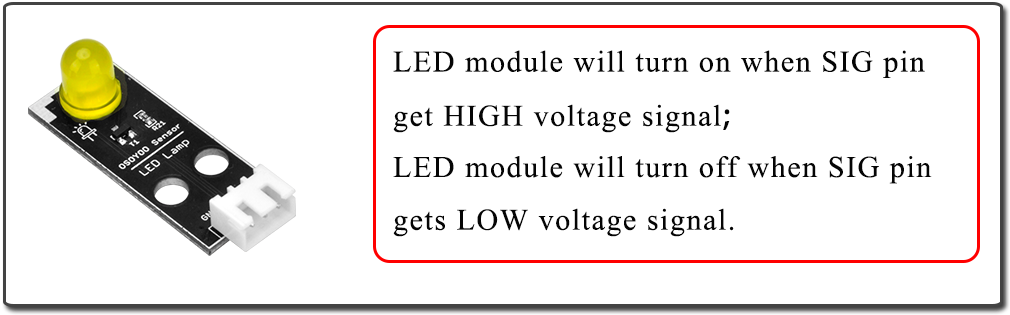
LED module will be turn on when SIG pin get HIGH voltage signal and will turn off when SIG pin gets LOW voltage signal.
OSOYOO UNO Board (Fully compatible with Arduino UNO rev.3) x 1
OSOYOO Magic I/O Shield for Arduino x 1
OSOYOO Button Module x 1
OSOYOO LED Module x 1
OSOYOO 3-Pin PNP Cable x 2
USB Cable x 1
PC x 1
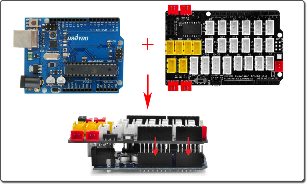
First, please plug Osoyoo Magic I/O shield into UNO board. Then connect the Button and LED module to the D2 and D8 port of the Magic I/O shield with a 3-pin PNP cable as below:
Notice: Shut off your battery or Unplug your power adapter when upload sketch code to OSOYOO Basic Board for Arduino.
You can download the code directly, then click “Open” in Mixly to choose the code you download:
After above circuit installation is completed, connect the OSOYOO Basic Board for Arduino to your computer using the USB cable. The green power LED (labelled PWR) will turn on.
We have learnt how to make an LED blink in last lesson. So in this one we will add a button to control the LED on/off.
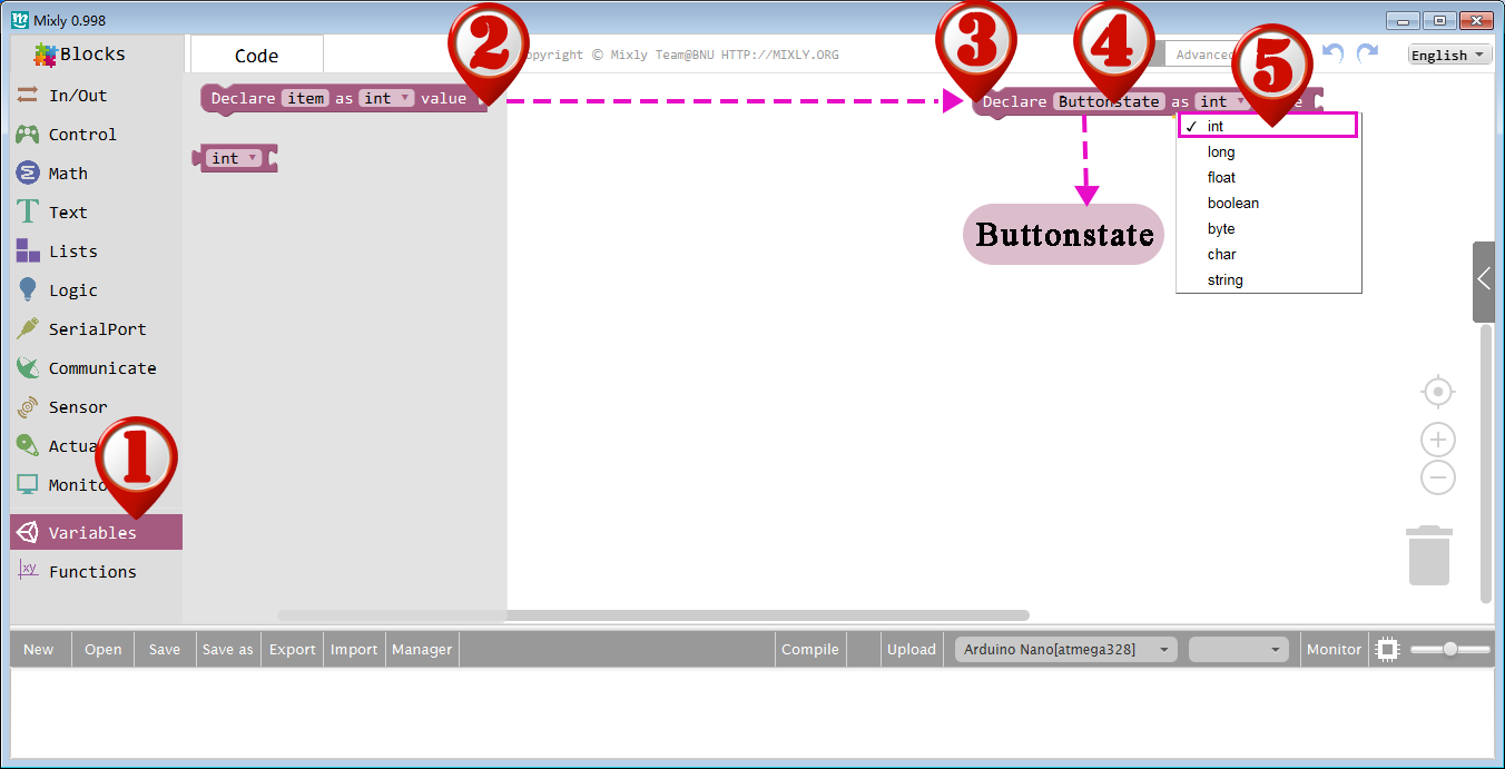
First, we need to declare a variable to show the Buttons state. Drag out a Declare block in Variables category.
Name this variable to Buttonstate, and select the type to int.
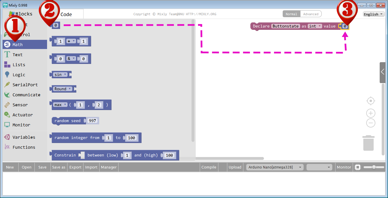
To assign 0 to Buttonstate initially, drag out the “0” block(the first block) in Math, and add it behind the Buttonstate. The value in the block can be changed, here we use its default value “0”.
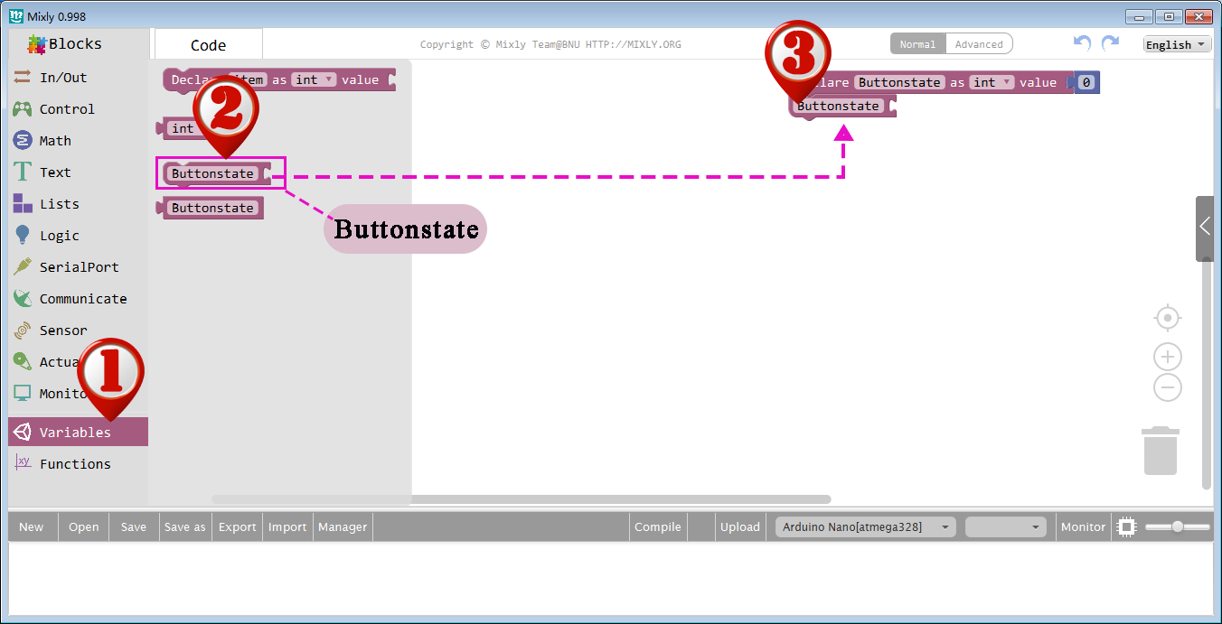
Now we need find some way to get value from D2 port and give it to Buttonstate variable. To do this, please click Variables category again, drag a Buttonstate block to blank area as follow picture:
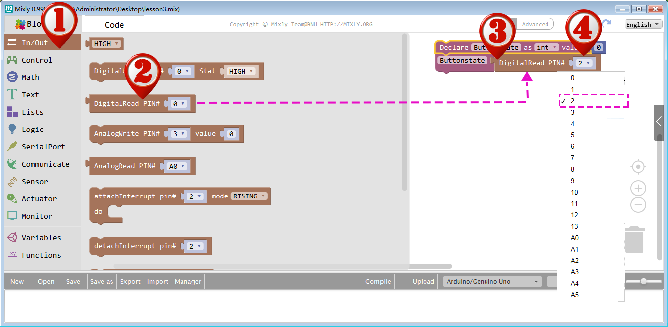
Then go to In/Out category, drag a digitalRead block and drop it behind the Buttonstate block and combine them together. Now you need set the PIN# to 2 which means you will assign input signal from PIN# 2 to Buttonstate variable.
Now let’s explain our control logic to OSOYOO Basic Board for Arduino. We want to turn on LED when we press button and turn off LED when button is released. Let’s use Graphic Blocks to give our logic to OSOYOO Basic Board for Arduino:
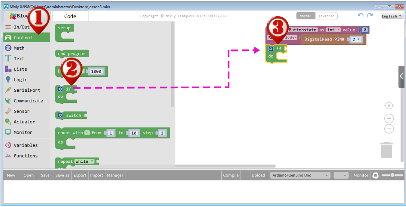
First , we drag an if do block in Control category right below Buttonstate block as following picture
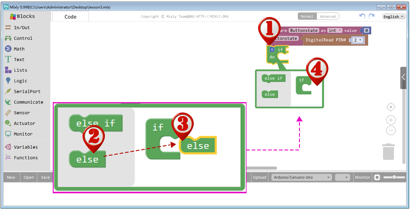
We also need add a else sub-block to this if do block. To do this, just click the setting icon inside if do block, drag out an else sub-block and connect it to if block, then Click setting again to turn off the setting window.
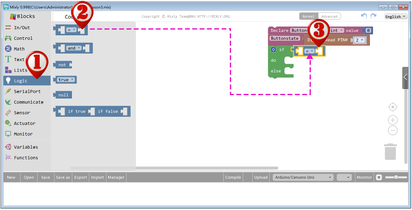
Next, we should add the condition logic block into above if do else block. To do this, Drag out the first “=” block in Logic category, and drop it to the right side of if slot as showed below.
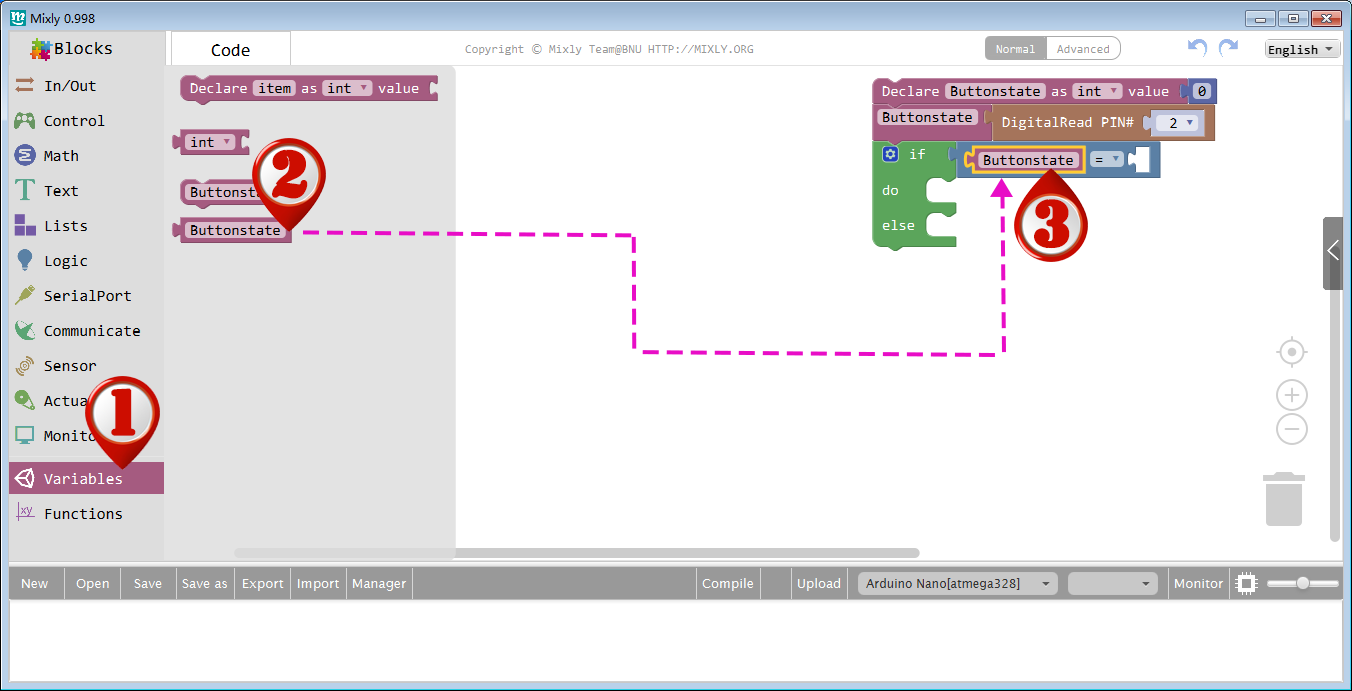
Drag out a Buttonstate block from Variables category, and drop it to the left slot of = block as showed below.
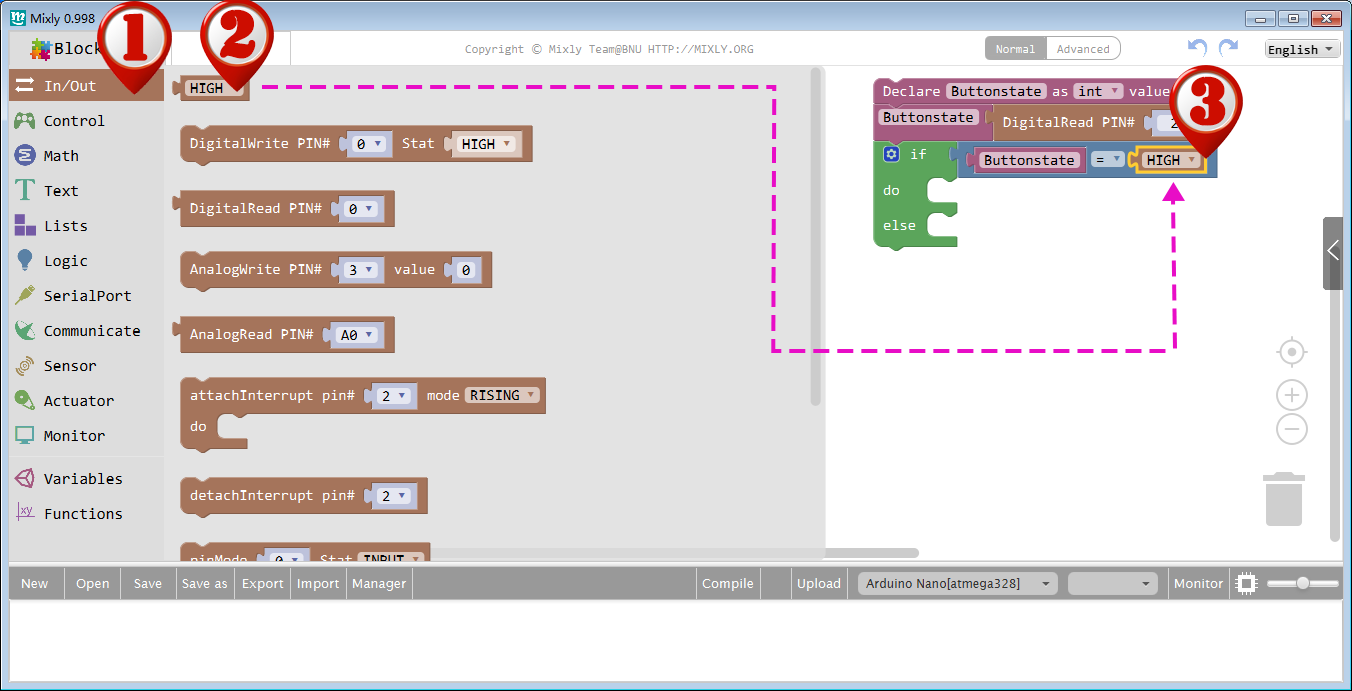
Drag out the HIGH block in In/Out section, and drop it to the right slot of the “=” block as showed below.
Now, the if else logic structure is completed.
Next we need to set the action when Buttonstate is in HIGH situations.
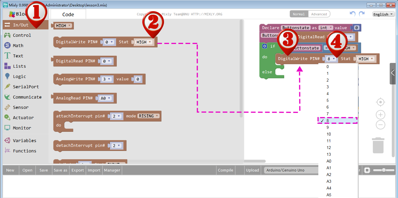
Drag a DigitalWrite block from In/Out section and drop it on the right side of do slot, then set PIN# to 8 and Stat value to HIGH as showed below:
Next we need to set the action when Buttonstate is in LOW situations.
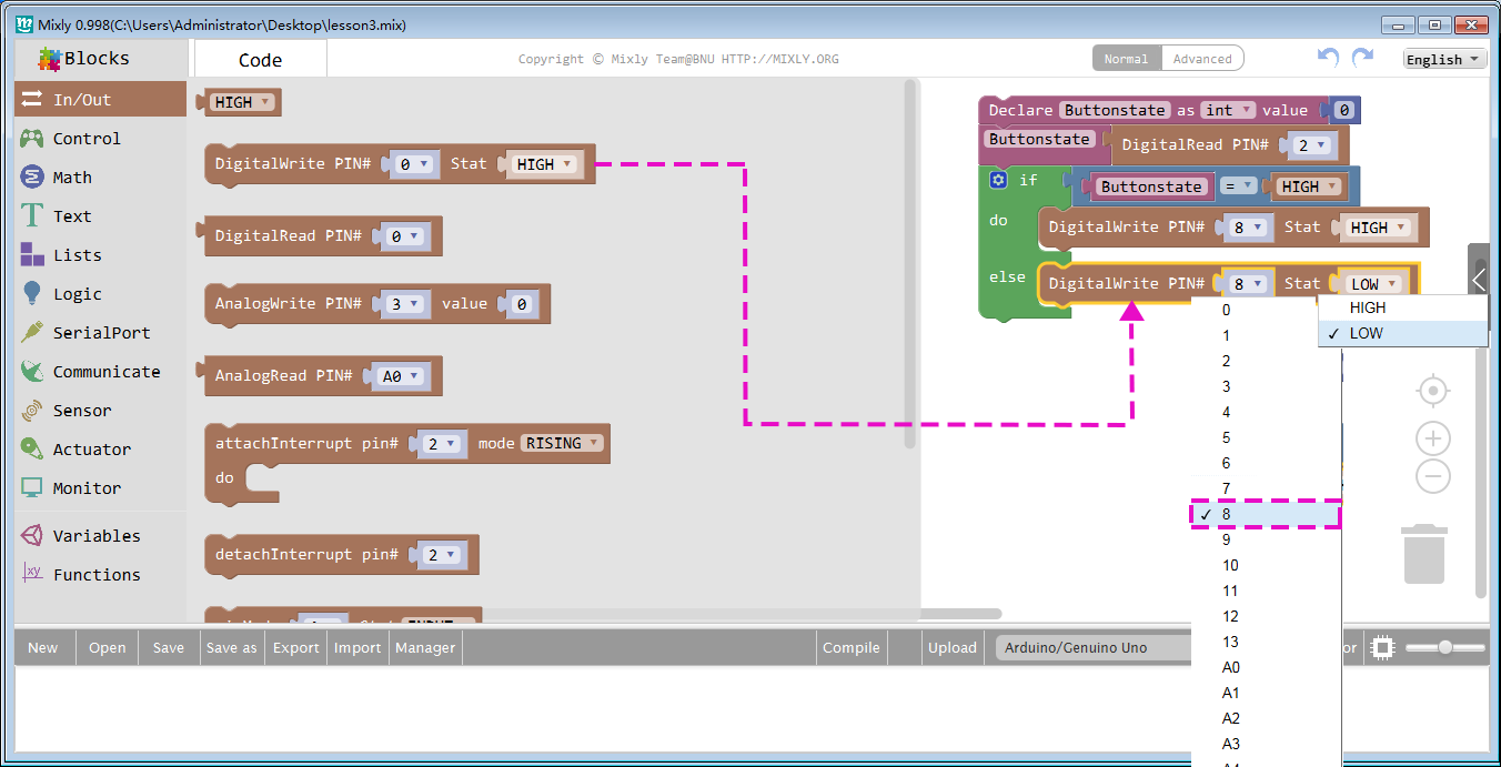
Drag another DigitalWrite block from In/Out section and drop it on the right side of else slot, then set PIN# to 8 and Stat value to LOW as showed below:
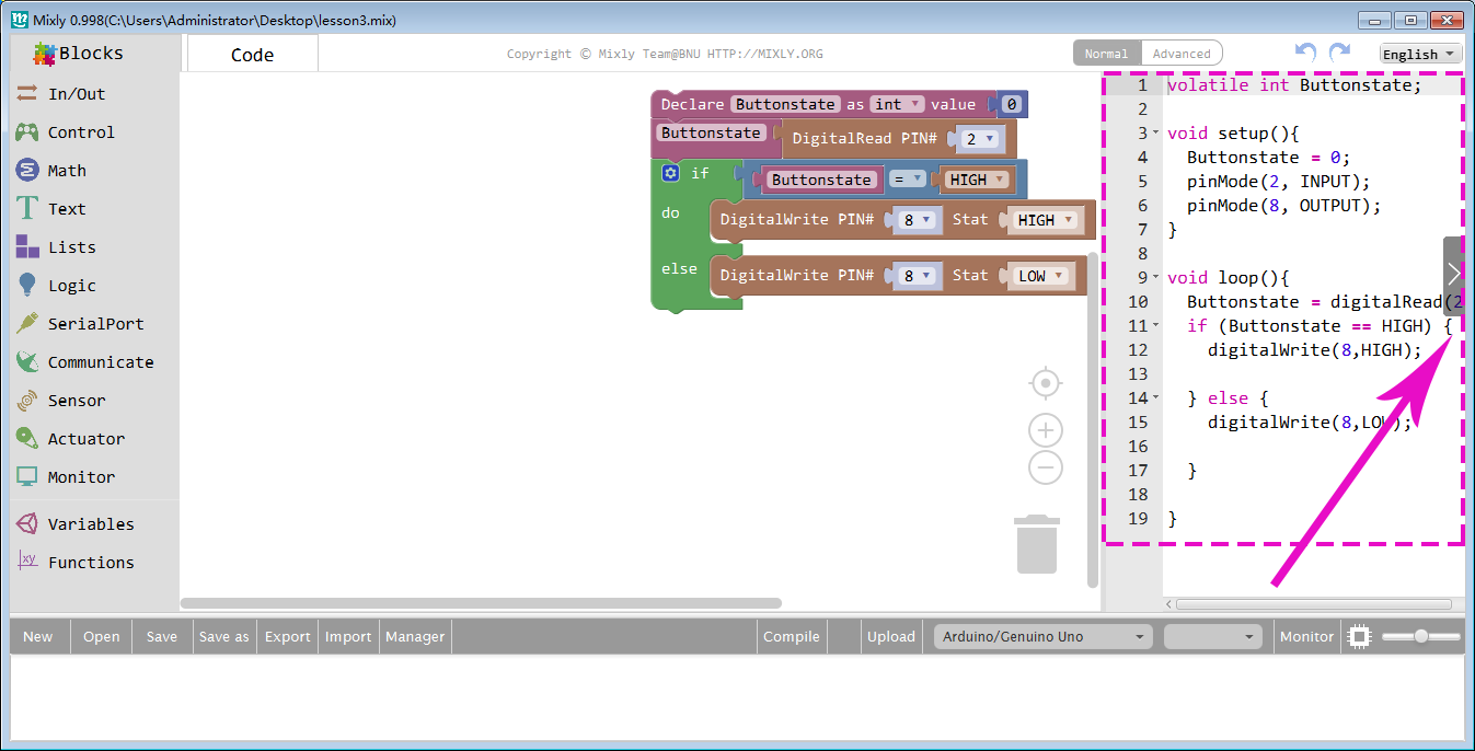
The whole program has complete. You can check equivalent Arduino C language code on the right bar.
The logic of our program is very simple: When we push Button Switch on D2 slot, OSOYOO Basic Board for Arduino Buttonstate variable will get a HIGH value. When Button is released, Buttonstate will get a LOW value.
When Buttonstate value is HIGH, then OSOYOO Basic Board for Arduino will give D8 a HIGH voltage and turn on LED, if Buttonstate value is LOW, then D8 will output a LOW voltage and turn off LED.
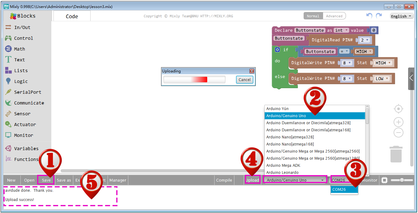
Click Save after all the programming is done. Select correct board type and serial port and then click upload. Finally, the staus will change to “Upload success!” as showed below.
Now, press the button, and the LED module will light up. When the switch is released, the LED turns off.
To add LED sensors and buttons to this project, use the same logic as this program. When you press the button switch, one or two LEDs will light up. When you release the switch, the LED turns off.


 Now, the if else logic structure is completed.