Overview
This tutorial introduce how to design a sound and light switch with raspberry pi. The sound and light switch turns on and off via Sound decibel and light value. When the light value is under the setting value in the code, meanwhile,
the sound is over the setting decibel, the switch will turn on. In this project, the raspberry pi receive the signal from sound sensor module and light sensor module, and then analyze the signal to control the switch, the switch means a
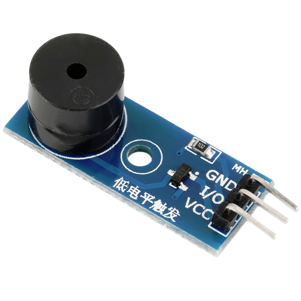
software switch (controlled by software). when the switch turn on, you will hear buzzer sound.
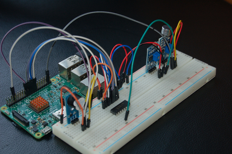
Experimental photo:
Experimental Parts
|
|
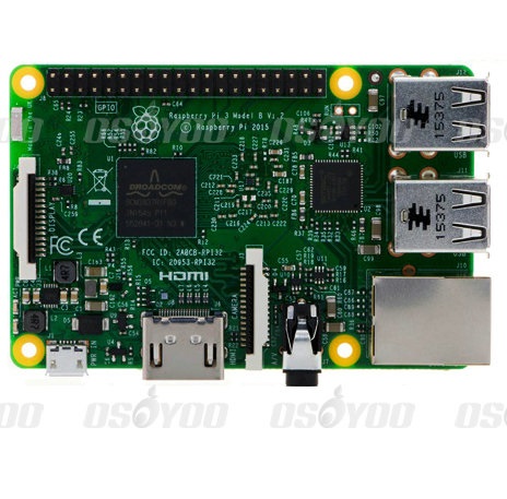
Raspberryp Pi 3
|
x1
|
|
|
Buzzer module
|
x1
|
|
|
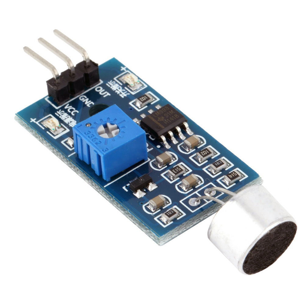
Sound sensor Module
|
x1
|
|
|
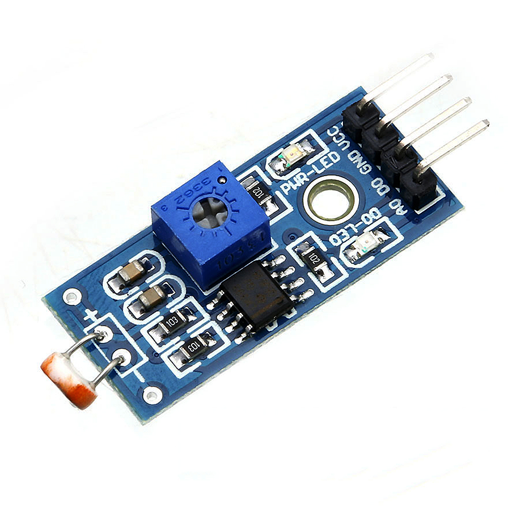
Light sensor module
|
x1
|
|
|
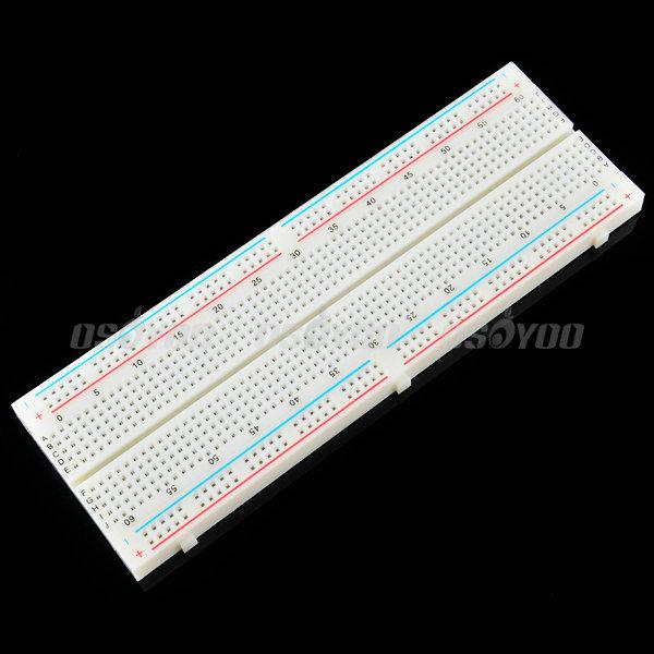
breadboard
|
x1
|
|
|
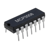
I/P Analog To Digital Converter
|
x1
|
|
|
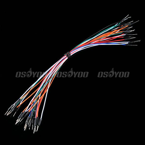
Male to Male Jumper wire
|
certain amount
|
|
|
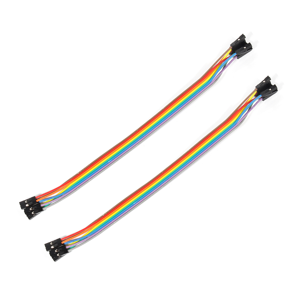
Female to Male Jumper wire
|
certain amount
|
Hardware
Raspberry Pi can work as a micro PC. the raspberry pi can handle digital signal, but when it handle Analog signal from such as thermistor, Potentiometer etc, it need a Analog To
Digital Converter. In this project, we use MCP3008 to convert voltage value signal from light sensor to digital signal. Raspberry pi control buzzer according to the digital value after converting. MCP3008 is a 10Bit
8-Kanal SPI Interface IC CHIP.
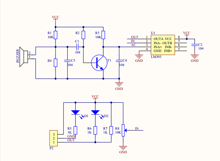
Sound sensor module can detect not only sound, but also the sound or special frequency. It can be adjusted via the blue Potentiometer. This sensor module can work under 3.3V and
5V, but the raspberry Pi GPIO output 3.3V generally, so the sensor connect with 3.3V GPIO. This module can output digital signal “0” and “1”. When the module detect the sound below value of the code, D0 pin of the module will output high
level. else, D0 will output low level.
Sound sensor module Schematic as follow:
Circuit Graph
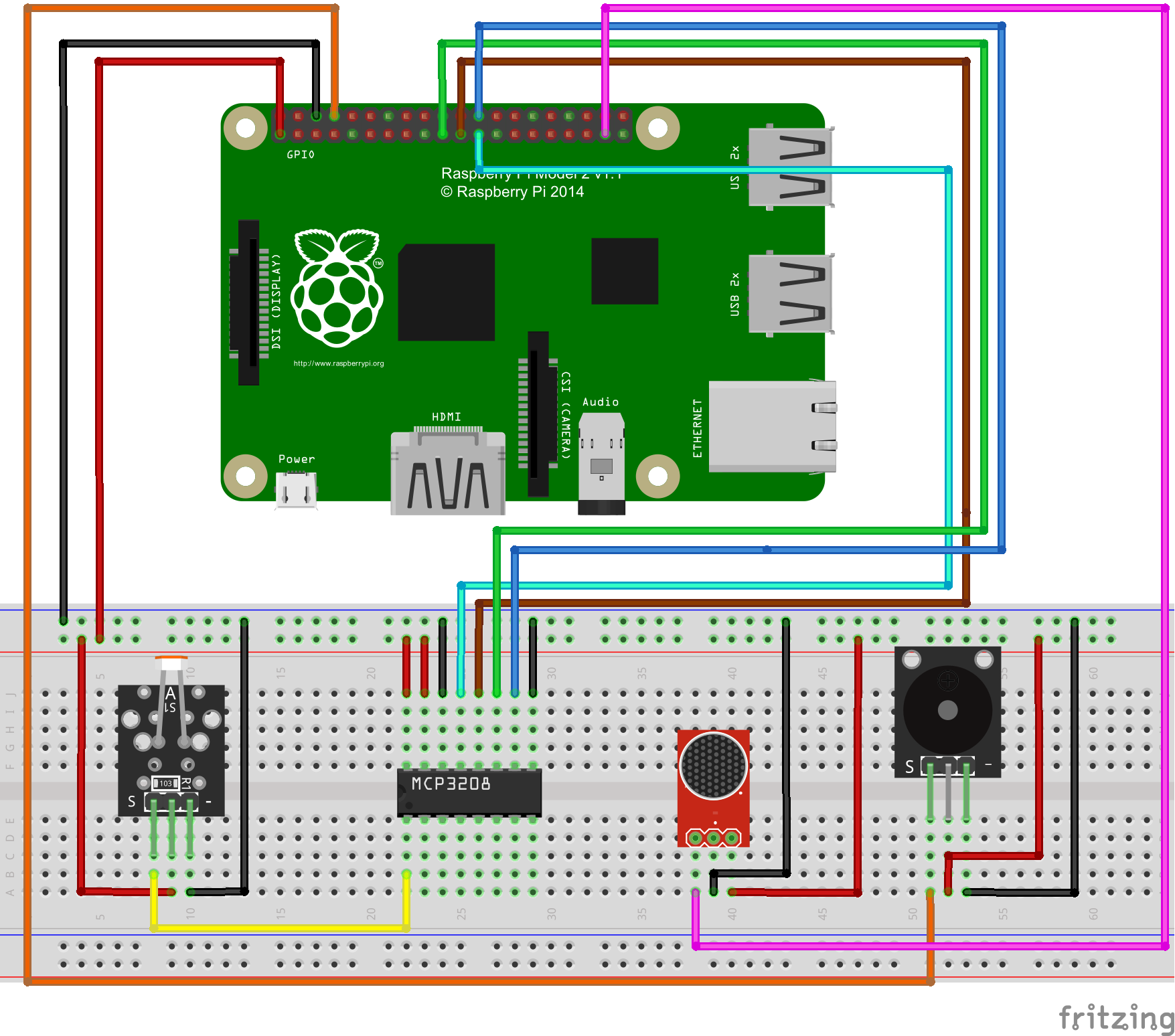
If you don’t know what is GPIO layout, check our tutorial: How to read Raspberry Pi i/o pin diagram (GPIO pin graph)
Note: Please reversing +/- or incorrectly connecting can destroy your raspberry Pi.
Software
You can connect a monitor for your raspberry pi, or remote locate raspberry pi via SSH.
1)enter the following command to create a new file named alarm.py and save this file at direction: /home/pi, and then press enter
sudo nano alarm.py
2)paste the following code in the file “alarm.py”:
import RPi.GPIO as GPIO import time import os buzzer = 14 sound = 26 # change these as desired - they're the pins connected from the # SPI port on the ADC to the Cobbler SPICLK = 11 SPIMISO = 9 SPIMOSI = 10 SPICS = 8 def init(): GPIO.setwarnings(False) GPIO.setmode(GPIO.BCM) GPIO.setup(buzzer,GPIO.OUT) #GPIO.output(buzzer,GPIO.HIGH) GPIO.setup(sound,GPIO.IN,pull_up_down=GPIO.PUD_UP) # set up the SPI interface pins GPIO.setup(SPIMOSI, GPIO.OUT) GPIO.setup(SPIMISO, GPIO.IN) GPIO.setup(SPICLK, GPIO.OUT) GPIO.setup(SPICS, GPIO.OUT) pass #buzzer alarm def alarm(): GPIO.output(buzzer,GPIO.LOW) time.sleep(1) GPIO.output(buzzer,GPIO.HIGH) time.sleep(1) #read SPI data from MCP3008(or MCP3204) chip,8 possible adc's (0 thru 7) def readadc(adcnum, clockpin, mosipin, misopin, cspin): if ((adcnum > 7) or (adcnum < 0)): return -1 GPIO.output(cspin, True) GPIO.output(clockpin, False) # start clock low GPIO.output(cspin, False) # bring CS low commandout = adcnum commandout |= 0x18 # start bit + single-ended bit commandout <<= 3 # we only need to send 5 bits here for i in range(5): if (commandout & 0x80): GPIO.output(mosipin, True) else: GPIO.output(mosipin, False) commandout <<= 1 GPIO.output(clockpin, True) GPIO.output(clockpin, False) adcout = 0 # read in one empty bit, one null bit and 10 ADC bits for i in range(12): GPIO.output(clockpin, True) GPIO.output(clockpin, False) adcout <<= 1 if (GPIO.input(misopin)): adcout |= 0x1 GPIO.output(cspin, True) adcout >>= 1 # first bit is 'null' so drop it return adcout # photoresistor connected to adc #0 photo_ch = 0 def main(): init() time.sleep(2) print"will detect sonud and light signal" while True: photo_value = readadc(photo_ch, SPICLK, SPIMOSI, SPIMISO, SPICS) if (GPIO.input(sound) == False)and (photo_value>=650): #detected sound signal and light intensity is low print "Alarm!" alarm() time.sleep(1) elif (GPIO.input(sound) == False)and (photo_value<=650): #detected sound signal,but light intensity is high GPIO.output(buzzer,GPIO.HIGH) print "sound signal is detected ,but light intensity is high!" time.sleep(1) elif (GPIO.input(sound) == True)and (photo_value<=650): GPIO.output(buzzer,GPIO.HIGH) print "sound signal not detected ,light intensity is high!" time.sleep(1) elif (GPIO.input(sound) == True)and (photo_value>=650): GPIO.output(buzzer,GPIO.HIGH) print "sound signal not detected ,light intensity is low!" time.sleep(1) print "light intensity is: " + str("%.1f"%((1024-photo_value)/1024.*100))+"%" if __name__ =='__main__': try: main() except KeyboardInterrupt: pass GPIO.cleanup()
4) after compile the project, press “Ctrl” + “X” to save the code, enter “Y” to confirm saving, and press “enter” to exit the file editor
5) Enter the following command to compile the code(as the last 4 steps), and press “enter” to
complete compiling code:
sudo wget http://osoyoo.com/driver/alarm.py
Experiment Result:
enter the following command to run python program
sudo python ./alarm.py
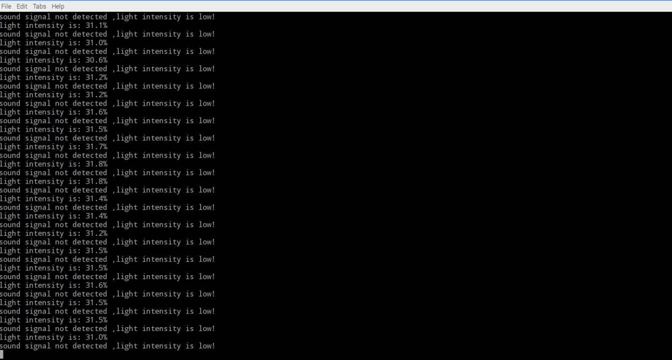
When cover light sensor and make loud sound at the same time, you will hear Intermittent buzzer sound. If uncover the light sensor or stop making loud sound, the buzzer will stop sound. This is the experimental result of sound and light switch.