Note: ALL OSOYOO Products for Arduino are Third Party Board which is fully compatitable with Arduino
Content
- Introduction
- Preparations
- About the Sound Detection Sensor
- Examples
Introduction
The Sound Detection Sensor is a small board that combines a microphone and some processing circuitry, it has the ability to detect different sizes of sound. This sensor can be used to for a variety of uses from industrial to simple hobby or playing around.
In this lesson we will guide you through hooking up and using the Sound Detector. It will examine how the circuit works, explain some details about getting the best performance from the Sound Sensor, then present some projects that demonstrate how to use it.
Preparations
Hardware
- Osoyoo Basic Board (Fully compatible with Arduino UNO rev.3) x 1
- Sound Detection Sensor x 1
- Breadboard x 1
- Jumpers
- USB Cable x 1
- PC x 1
Software
- Arduino IDE (version 1.6.4+)
About Sound Detection Sensor
Overview
The Sound Detection sensor module has a built-in capacitive electret microphone which is highly sensitive to sound. Sound waves cause the thin film of the electret to vibrate and then the capacitance changes, thus producing the corresponding changed voltage, so it can detect the sound intensity in ambient environment. Since the change is extremely weak, it needs to be amplified. We use a LM393 as the power amplifier here. You can adjust the sensitivity with by adjusting the Potentiometer. When the sound level exceeds the set point, an LED on the sensor module is illuminated and the output is sent low.
Note: This sound sensor is used to detect whether there’s sound surround or not, it cannot recognize the frequence or volum, please don’t use the module to collect sound signal.
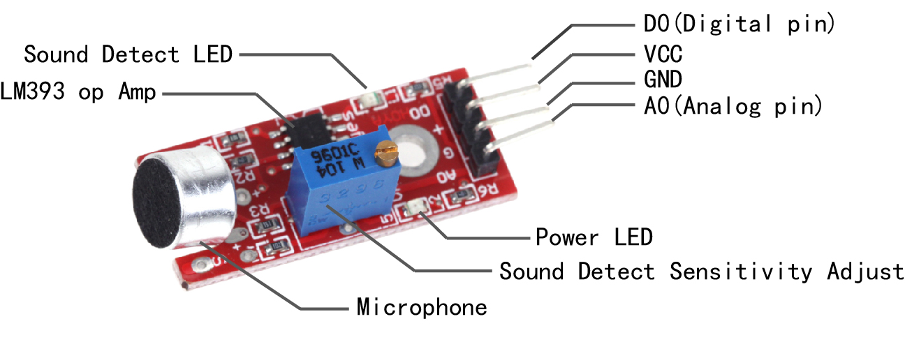
Sound Detection Sensor Pin Outs
The image and table below detail the controls, pin outs, and other key components.
When referring sensititivity, well. I mean:
- When less sensitive, it takes more sound to trigger the device
- When more sensitive, it takes less sound to trigger the device
| Parameter |
Value |
| + |
5 V DC from your mainboard |
| G |
GND from your mainboard |
| D0 |
Connect to Digital Input Pin |
| A0 |
Connect to Analog Input Pin |
| Power LED |
Illuminates when power is applied |
| Sound Detect LED |
Illuminates when sound is detected |
| Potentiometer |
CW = More Sensitive
CCW = Less Sensitive |
It has four pins that needs to be connected to your mainboard . The top one(if you look at the image above), is AO. This should be connected to the analog input 0 on the Arduin(A0). The one beside that is GND, which is connected to ground, the VCC is connected to +5V, and the last one is DO – which is the digital output of the module, and should be connected to digital pin 2 on the Arduin.
On the top of the sound sensor is a little flathead screw you can turn to adjust the sensitivity and analog output of the sound sensor. To calibrate the sound sensor you can make some noise and keep turning it until you start seeing the sensor-LED on the module starts blinking with the rhythm.
Uses for the Sound Detector
Given that this device measures whether or not sound has exceeded a threshold, you’re basically left with determining what it is you want to do. What I mean by this is that you can do something when it is quiet and/or you can do something when it is loud. For example:
- You could detect whether or not a motor is running.
- You could set a threshold on pump sound so that you know whether or not there is cavitation.
- In the presence of no sound, you might want to create an ambiance by turning on music.
- In the presence of no sound and no motion, you may go into an energy savings mode and turn off the lights.
Examples
Digital Detect Sound Sensitive Lights
In this example, we are going to connect the Sound Detection sensor module to the Arduin digital pin to control the on-board LED, so that the LED will light up every time the sensor detects sound.
Note: The sensitivity of the Sound Detection sensor is adjustable – you may adjust it by the potentiometer.
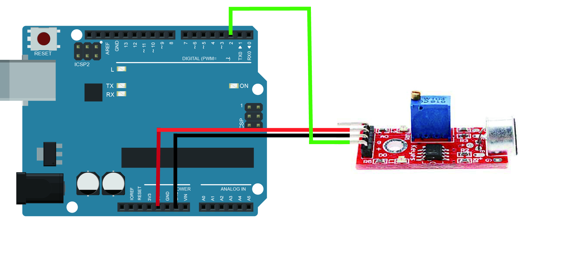
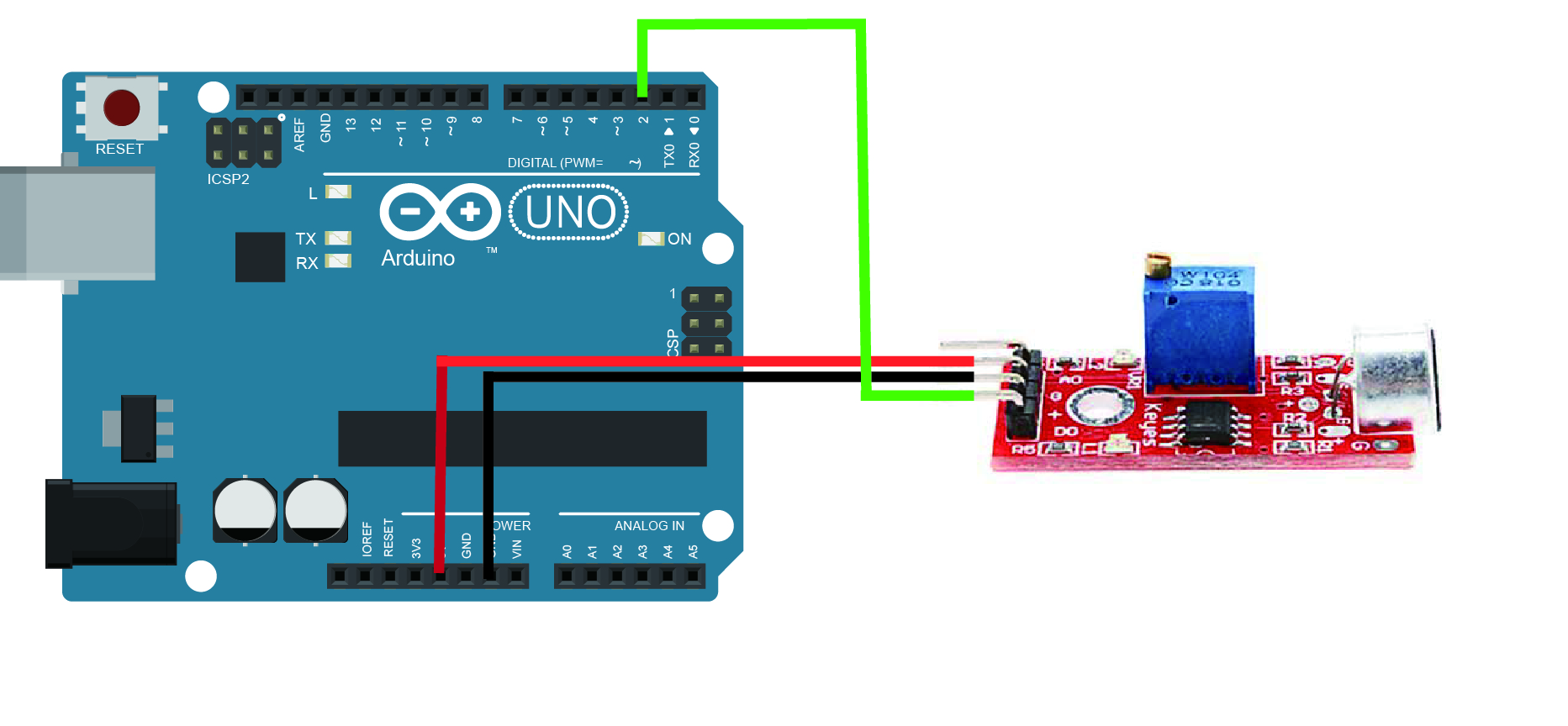
Connection
Overhere we use the D2 as the digital pin to connect with the sound sensor, build the circuit as below:
Code Program
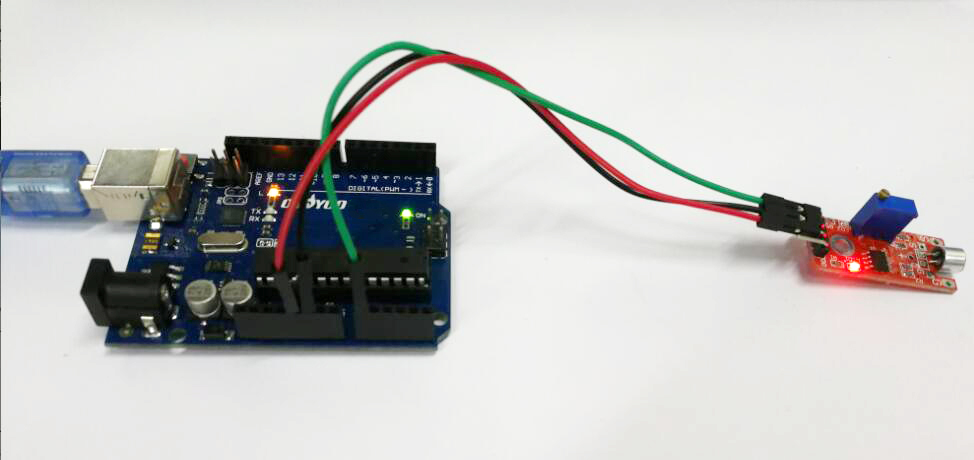
After above operations are completed, connect the board to your computer using the USB cable. The green power LED (labelled PWR) should go on.Open the Arduino IDE and choose corresponding board type and port type for you project. Then load up the following sketch onto your board.
int digit_sensor = 2; // select the input pin for the potentiometer int ledPin = 13; // select the pin for the LED int digitValue ; // value from the digit input pin void setup () { pinMode (ledPin, OUTPUT); pinMode (digit_sensor, INPUT); Serial.begin (9600); } void loop () { digitValue=digitalRead(digit_sensor); if (digitValue==LOW) { digitalWrite (ledPin, HIGH); delay(50); } else { digitalWrite (ledPin, LOW); delay(10); } }
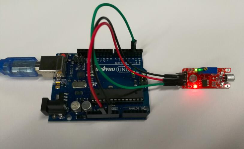
Running Result
A few seconds after the upload finishes, you can clap or knock something next to the sensor, when the volume reaches to a certain value, the LED attached to pin 13 on the Osoyoo Uno board will light up.
Note: If the LED is not lighting up or the LED is always bright, you need to change the sensor sensitivity by rotating the potentiometer.
Analog Detect Sound Sensitive Lights
In this example, we will show how to use the analog pin to detect the sound. The microphone sensor will detect the sound intensity of your surroundings and will light up an LED if the sound intensity is above a certain threshold.
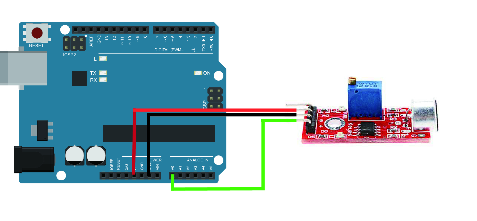
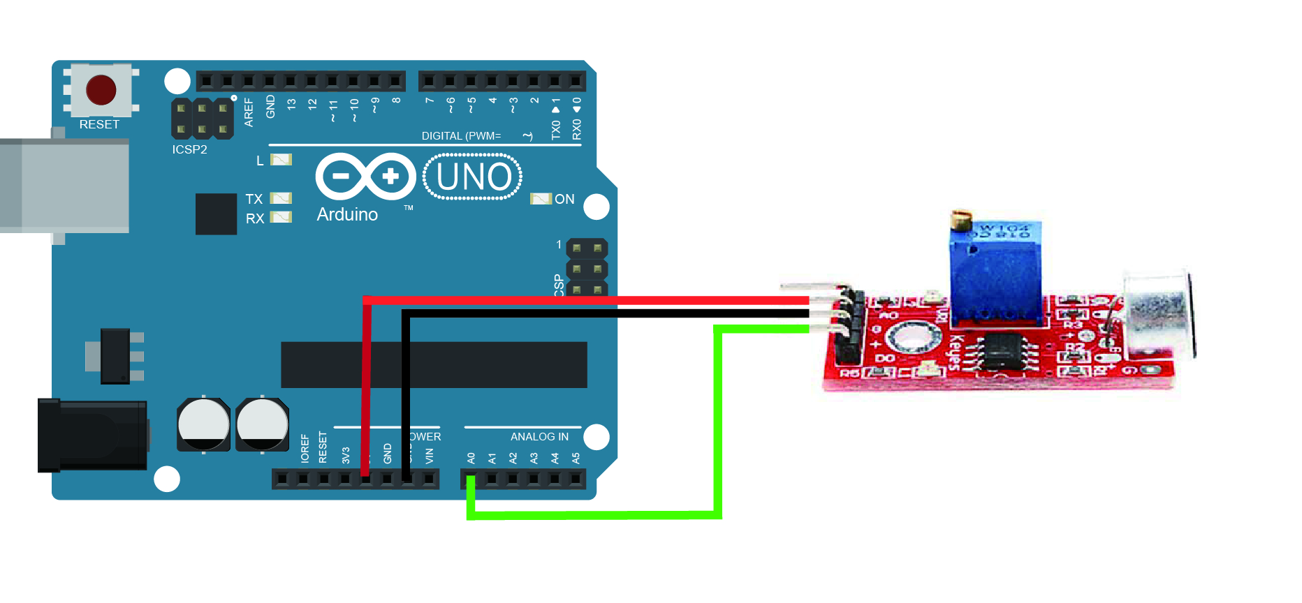
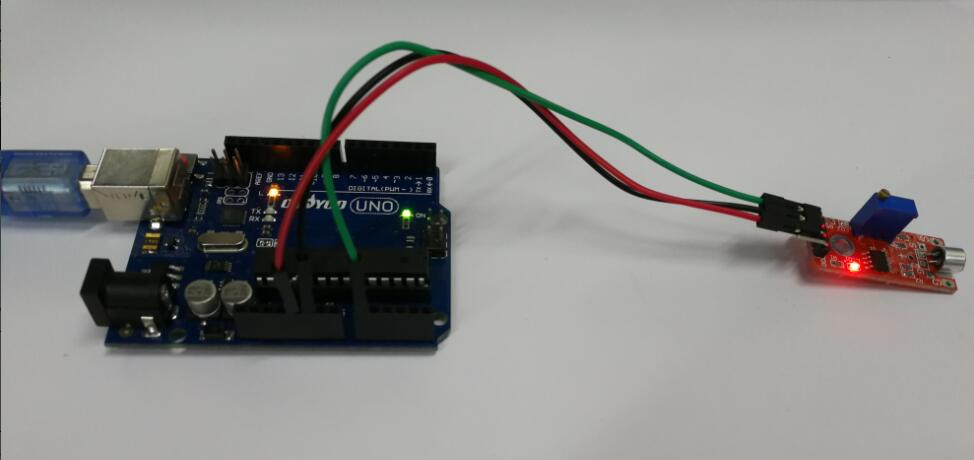
Connection
Overhere we use the A0 as the analog pin to connect with the sound sensor, build the circuit as below:
Code Program
After above operations are completed, connect the board to your computer using the USB cable. The green power LED (labelled PWR) should go on.Open the Arduino IDE and choose corresponding board type and port type for you project. Then load up the following sketch onto yourboard.
const int ledPin = 13; //pin 13 built-in led const int soundPin = A0; //sound sensor attach to A0 int threshold = 600; //Set minimum threshold for LED lit void setup() { pinMode(ledPin,OUTPUT);//set pin13 as OUTPUT Serial.begin(9600); //initialize serial } void loop() { int value = analogRead(soundPin);//read the value of A0 Serial.println(value);//print the value if(value > threshold) //if the value is greater than 600 { digitalWrite(ledPin,HIGH);//turn on the led delay(200);//delay 200ms } else { digitalWrite(ledPin,LOW);//turn off the led } delay(1000); }
This is the code to make a LED blink with sound. You have to set the threshold so it’ sensible enough to make the led blink, you can also see the value of sound intensity on Serial Monitor.
Running Result
After copying and uploading this code, when the volume reaches to a certain value, the LED attached to pin 13 on the Uno board will light up. If the sound does not sense very well, try changing the threshold value or changing the sensor sensitivity by rotating the potentiometer.
You can open the Serial Monitor by going to Tools > Serial Monitor or pressing the magnifying glass-button in the software window.
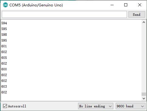
What prints out is the analog and digital values of from the sound sensor module. The analog value should spike up when a noise occurs and stabilize when it gets quiet again. Now in the code there is an “int threshold = 600;” line that needs to be changed to something very close but higher than the value you get from the Serial Monitor when it is quiet around you. For instance if you see an analog value of 500, then threshold should be changed to perhaps 503 or 505. When a sound occurs, the analog value will rise and go above the threshold value. When that happens your LEDs will turn on. When it gets quiet again the analog value will go back to 503 and the LEDs go dark again.


I couldn’t see the full code program.