Questa lezione è il nostro progetto finale, un po’ più complicato ed emozionante. Nella lezione precedente, abbiamo usato solo un browser o un telefono cellulare per far parlare gli esseri umani. In questa lezione, utilizzeremo una scheda madre per comunicare con un’altra scheda madre attraverso il protocollo Internet UDP. È necessario acquistare due set di kit di apprendimento IoT. Utilizzeremo la prima scheda di base OSOYOO (chiamata basic A) per collegare un sensore di movimento PIR e un’altra scheda principale (basic B) per collegare un cicalino. Quando il sensore di movimento PIR della scheda base A rileva un intruso, un segnale di allarme viene inviato dalla scheda base A alla scheda base B e il cicalino emette un segnale acustico.
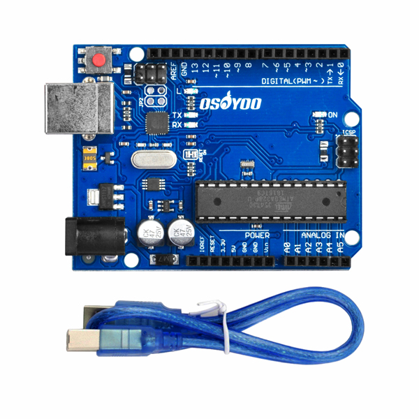
OSOYOO Scheda base x 2
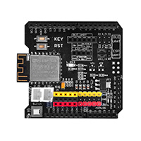
OSOYOO ESP8266 Wi-Fi Shield x 2
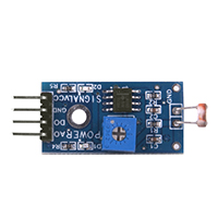
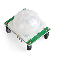
HC-SR501 Sensore di movimento PIR x 1
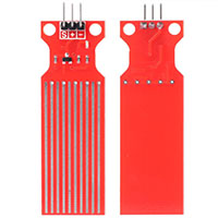
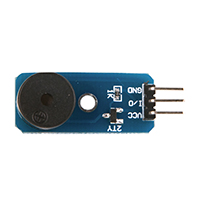
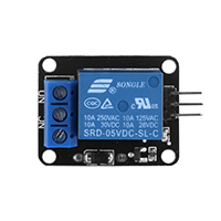
Modulo sensore buzzer x 1
Cavo USB x 2
Fili di ponticello
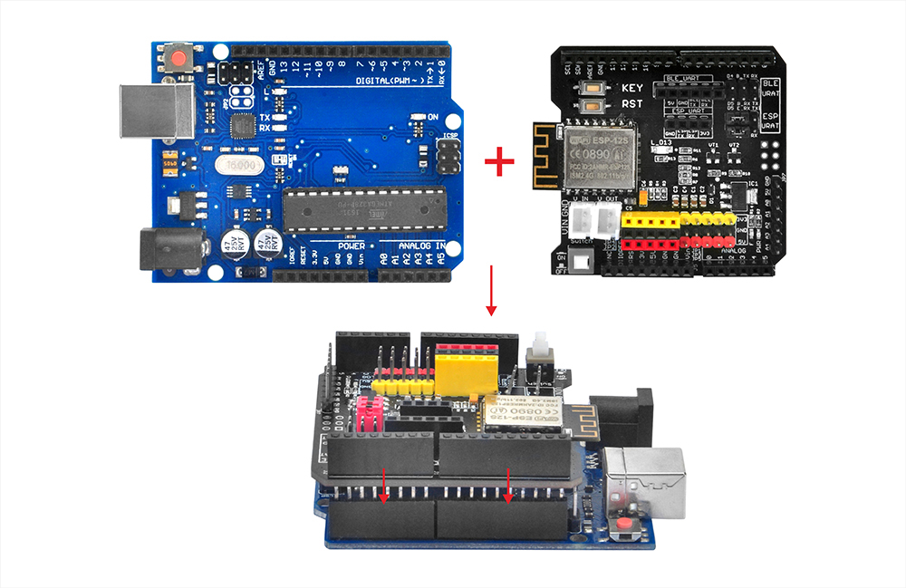
Inserite l’ESP8266 Wi-Fi Shield nella vostra scheda madre
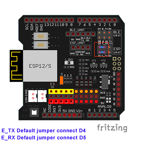
Assicurarsi che il cappuccio del ponticello sia collegato da E_TX a D4 e da E_RX a D5.
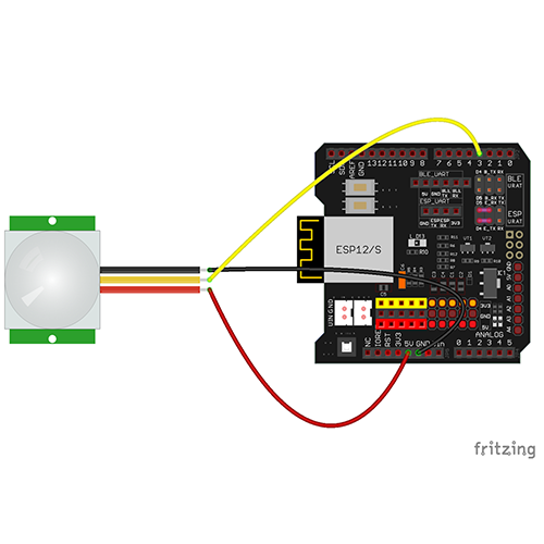
Hardware A) Collegare la scheda base OSOYOO+ESP8266 Wi-Fi shield al sensore di movimento PIR. Il pin OUT centrale del sensore di movimento si collega a D3.
OSOYOO Scheda base
PIR
D3
OUT
GND
GND
5V
VCC
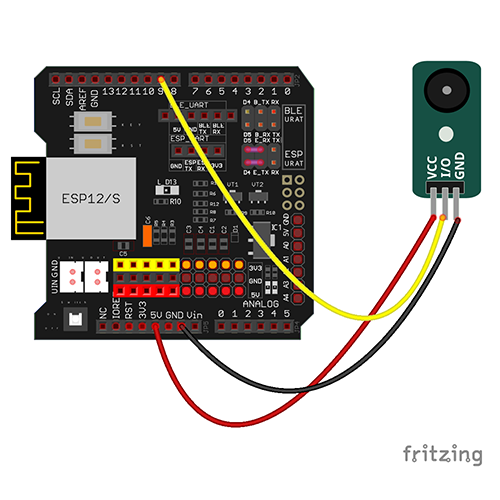
Hardware B) Collegare lo schermo Wi-Fi OSOYOO Basic Board B+ESP8266 al buzzer. Il pin I/O del cicalino si collega a D9.
OSOYOO Scheda base
Buzzer
D9
I/O
GND
GND
5V
VCC
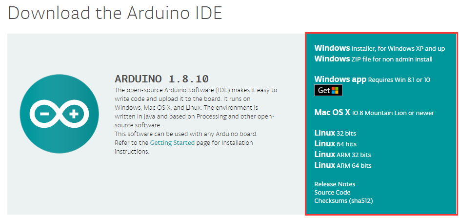
Passo A) Installare l'IDE più recente (se si dispone della versione IDE 1.1.16 o successiva, saltare questo passaggio). Scaricare l'IDE da
 https://www.arduino.cc/en/Main/Software?setlang=en e installare il software..
Fase B) Collegare la scheda di base OSOYOO al computer tramite un cavo USB.
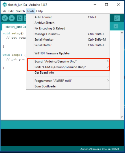
Fase C) Aprire l’IDE e scegliere il tipo di scheda e il tipo di porta corrispondenti al progetto.
Board:”Arduino/Genuino UNO”
Port: Scegliere la propria porta seriale per la scheda madre
Dopo aver decompresso il file di cui sopra, verrà visualizzata una cartella, “esp8266-lesson12”. Entrate in questa cartella e vedrete due sottocartelle (buzzer e motion sensor).
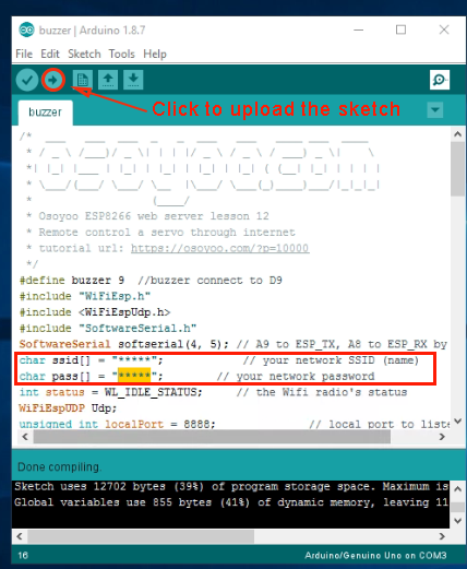
Entrate nella cartella buzzer e fate doppio clic sul file buzzer.ino, trovando le seguenti righe:
char ssid[] = "******"; // your network SSID (name)
char pass[] = "******"; // your network password
Sostituire ****** con l'SSID e la password Wi-Fi corretti, altrimenti il progetto non potrà collegarsi a Internet.
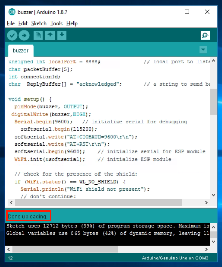
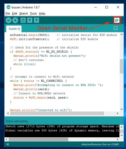
Fase E) Dopo aver modificato le linee precedenti, caricare lo sketch nell'IDE.
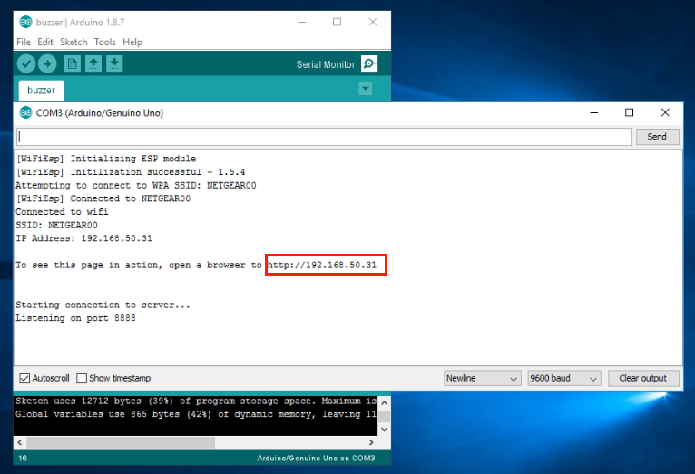
Aprite il vostro Serial Monitor e vedrete che il router assegnerà un indirizzo IP all’IDE come segue:
Nell’esempio precedente, 192.168.50.31 è l’indirizzo IP assegnato dal router al buzzer IDE. È necessario annotare questo indirizzo IP su carta. Dobbiamo usare questo indirizzo IP per modificare il codice dello sketch nel file motionsensor.ino.
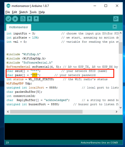
È possibile scollegare l’IDE dal PC e utilizzare un altro adattatore USB per alimentare l’IDE del cicalino. Fase F) Ora, collegare l’IDE del sensore di movimento PIR al PC, aprire la cartella motionsensor e aprire il file motionsensor.ino, trovando le seguenti righe:
char ssid[] = "******"; // your network SSID (name)
char pass[] = "******"; // your network password
Sostituire ****** con l’SSID e la password Wi-Fi corretti, altrimenti il progetto non potrà collegarsi a Internet.
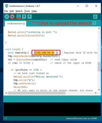
Fase 5) Cercare quindi la riga seguente:
byte remoteIp[] = { 10,0,0,244 }; //...
È necessario modificare la variabile remoteIp[] della riga, sostituendo l’indirizzo IP 10.0.0.244 con quello registrato dal passaggio A. Nel nostro esempio, il passaggio A mostra che l’IP del cicalino è 192.168.50.13, quindi si crea la riga:
byte remoteIp[] = { 192,168,50,31 }; //…
Quindi è possibile compilare e caricare il file motionsensor.ino nell’IDE.
Risultato del test:
Accendere sia lo shield ESP8266 che le schede OSOYOO Basic. Quando si muove la mano davanti al sensore di movimento, il cicalino remoto emette un segnale acustico.