In this lesson, we will show how to gradually change the luminance of an LED through programming. Since the pulsing light looks like breathing, we give it a magical name – breathing LED. We’ll accomplish this effect with pulse width modulation (PWM).
Preparations
Hardware
OSOYOO UNO Board (Fully compatible with Arduino UNO rev.3) x 1
OSOYOO Magic I/O Shield for Arduino x1
Red LED Module x 1
OSOYOO 3-Pin PnP cable x 1
USB Cable x 1
PC x 1
Software
Arduino IDE (version 1.6.4+)
What is PWM?
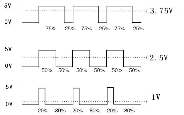
Pulse Width Modulation, or PWM, is a technique for getting analog results with digital means. Digital control is used to create a square wave, a signal switched between on and off. This on-off pattern can simulate voltages in between full on (5 Volts) and off (0 Volts) by changing the portion of the time the signal spends on versus the time that the signal spends off. The duration of “on time” is called the pulse width. To get varying analog values, you change, or modulate, that pulse width.
To get varying analog values, you change, or modulate, that pulse width. If you repeat this on-off pattern fast enough with an LED for example, the result is as if the signal is a steady voltage between 0 and 5V controlling the brightness of the LED. (See the PWM description on the official website of Arduino).
We can see from the top oscillogram that the amplitude of the DC voltage output is 5V. However, the actual voltage output is only 3.75V through PWM because the high level only takes up 75% of the total voltage within a period.
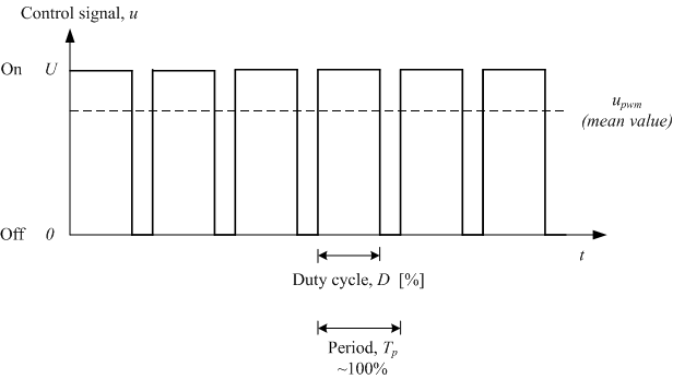
Here is an introduction to the three basic parameters of PWM:
uty cycle describes the proportion of “on” time to the regular interval or period of time.
Period describes the reciprocal of pulses in one second.
The voltage amplitude here is 0V–5V.
Connection
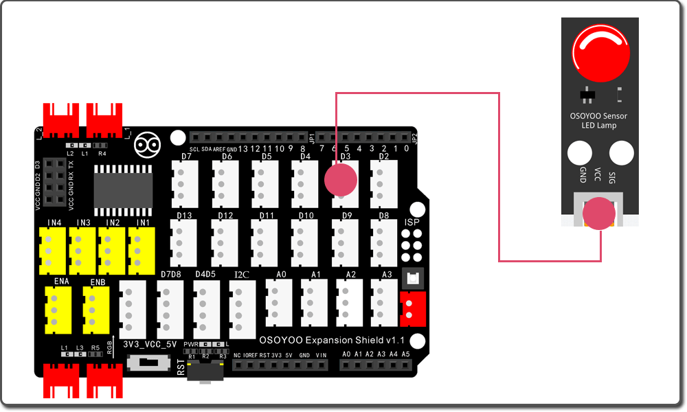
There are 6 pins on most Arduino boards marked with ‘PWM’ next to the pin number (on some boards it is an “~” symbol) – these pins are PWM pins.We use the pin D3 to control the LED module here.
First, please plug Osoyoo Magic I/O shield into UNO board:
Then connect the LED module to the D3 port of the Magic I/O shield with a 3-pin PNP cable as below:
Notice:
You cannot directly connect an LED to a battery or voltage source. Firstly, because the LED has a positive and a negative lead and will not light if they are the wrong way around and secondly, an LED must be used with a resistor to limit or ‘choke’ the amount of current flowing through the LED – otherwise the LED could burn out!
Upload Sketch
Connect the Arduino board to your computer using the USB cable. The green power LED (labelled PWR) should go on.
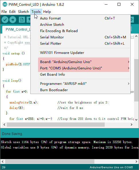
Open the Arduino IDE and select corresponding board type and port type for your Arduino board.
Now load the ‘PWM_Control_LED’ example sketch or copy below code to your new Arduino IDE window and upload it to your Arduino board. Wait a few seconds – you should see the RX and TX leds on the board flashing. If the upload is successful, the message “Done uploading.” will appear in the status bar.
voidsetup(){pinMode(3,OUTPUT);// declare pin 3 to be an output}voidloop(){for(inta=0;a<=255;a++)//loop from 0 to 255,it controls the increase in PWM brightness{analogWrite(3,a);//set the brightness of pin 3: delay(8);//wait for 8 ms }for(inta=255;a>=0;a--)//loop from 255 down to 0,it control PWM brightness reduction{analogWrite(3,a);// set the brightness of pin 3:delay(8);//wait for 8 ms}delay(800);//wait for 800 ms}
Running Result
A few seconds after the upload finishes, you should see the LED gets brighter and brighter, and then slowly dimmer, just like breathing.