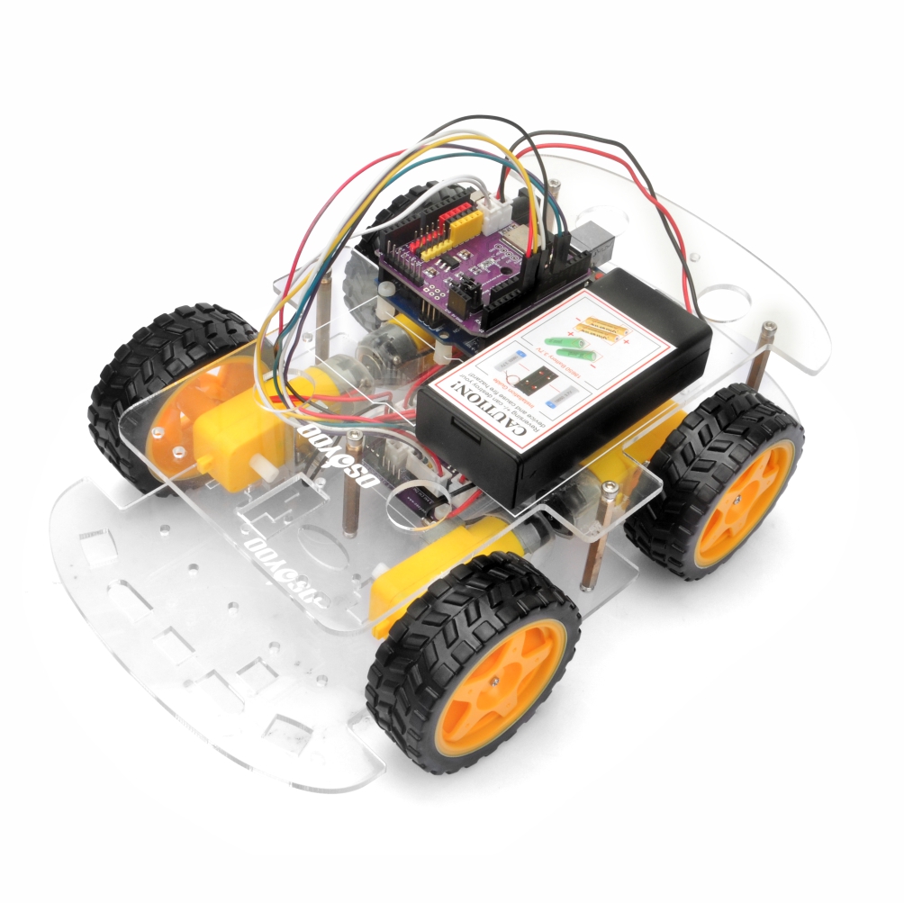
In questa prima lezione del kit OSOYOO V3 Robot Car, assemblerai il telaio e collegherai tutti i componenti principali. L’obiettivo è costruire una piattaforma per robot-car stabile e funzionante, pronta per le lezioni successive. Al termine di questa lezione, il microcontrollore, il driver del motore, il sistema di alimentazione e il telaio saranno tutti montati e pronti per il test.
2Componenti e dispositivi:
Per questo assemblaggio sono necessari i seguenti componenti. Assicurati di avere tutte le parti prima di iniziare.
N.
Immagine
Dispositivo
Q.tà
Accessori
Link
1
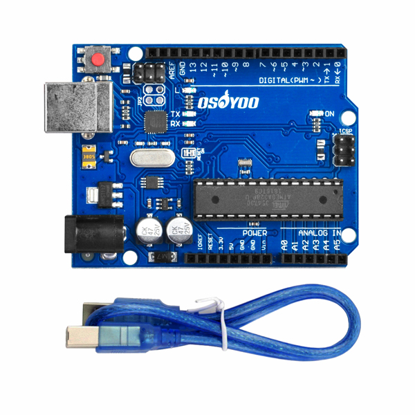
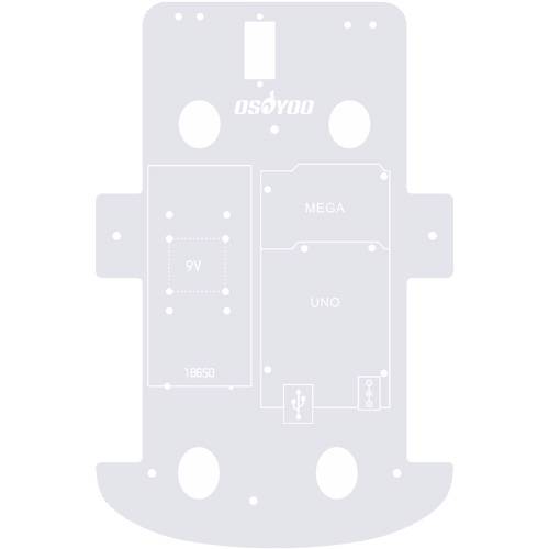
Scheda base OSOYOO
1
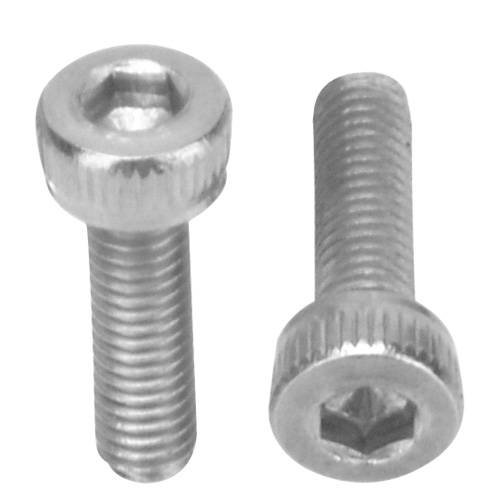
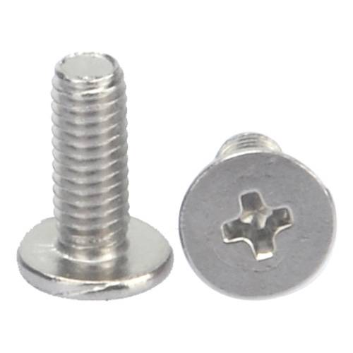
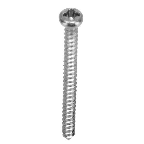
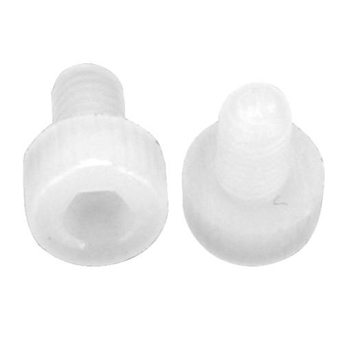
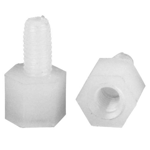
Vite M3 in plastica x 3
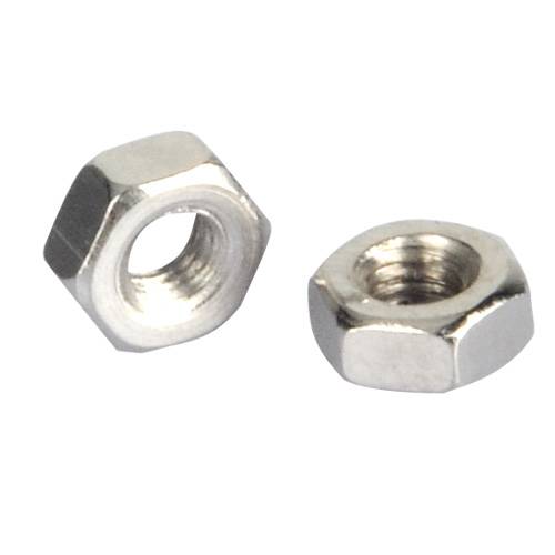
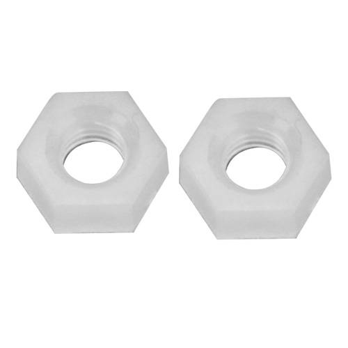
Dado M3 in plastica x 4
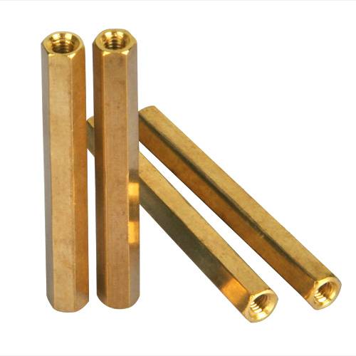
Distanziale M3 in plastica x 4
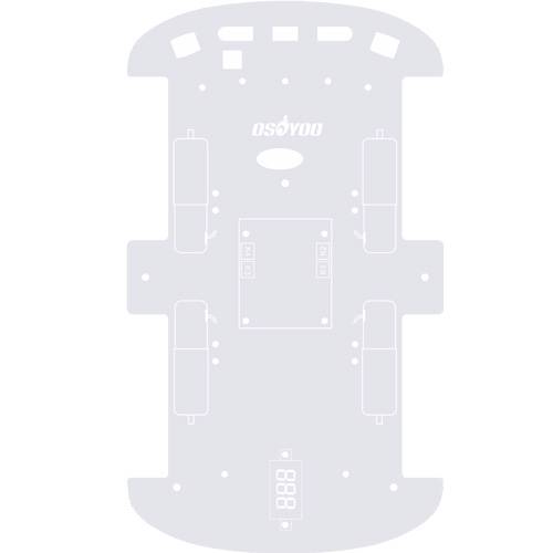
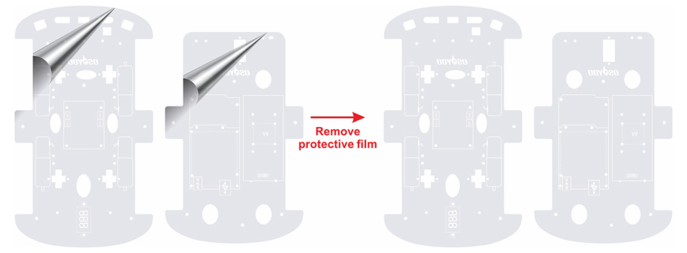
1) Rimuovi la pellicola protettiva dal telaio superiore e inferiore. (Ogni telaio ha una pellicola protettiva.)
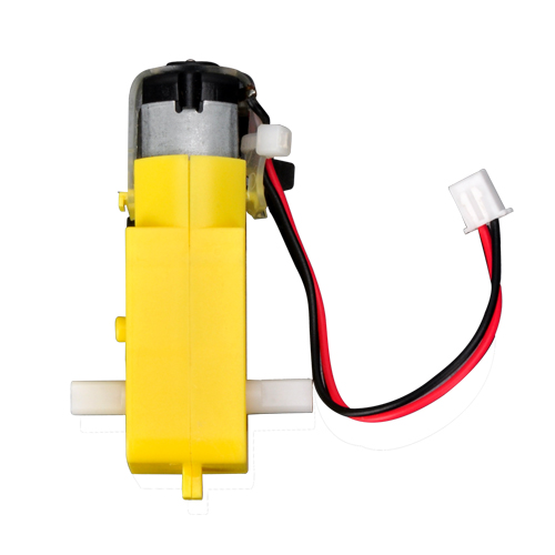
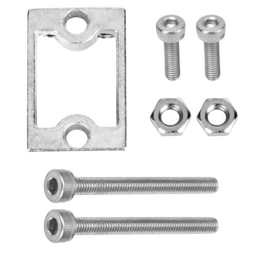
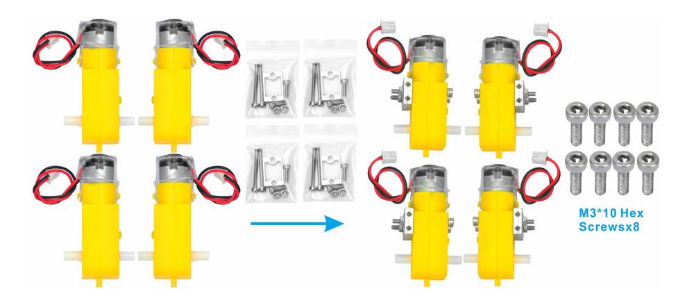
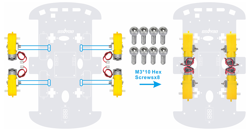
2) Fissa i 4 motoriduttori ai supporti metallici come mostrato di seguito. (Controlla la direzione del motore prima di installare i supporti metallici.)
3) Monta i 4 motori sul telaio inferiore usando viti esagonali M3*10 con il cacciavite Hex. (Le viti per questo passaggio sono incluse nella confezione dei supporti metallici per motore.)
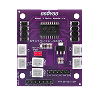
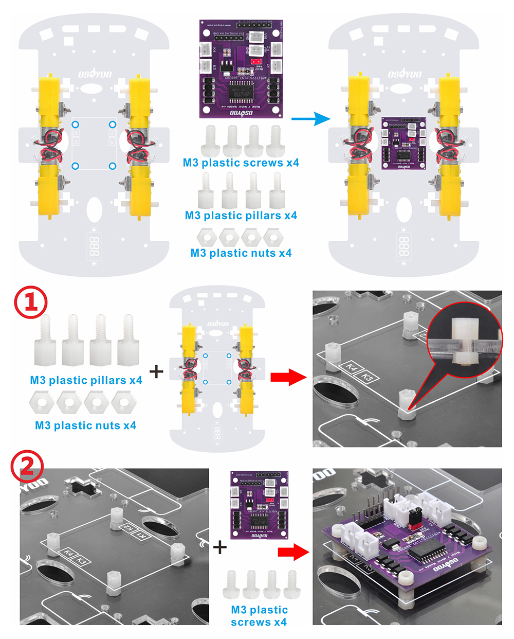
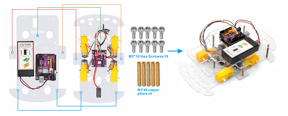
4) Installa il modulo OSOYOO Model V motor driver sul telaio inferiore usando 4 viti M3 in plastica, distanziali in plastica e dadi in plastica. (Assicurati che il modulo OSOYOO Model V motor driver sia installato nel verso corretto.)
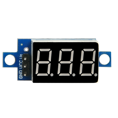
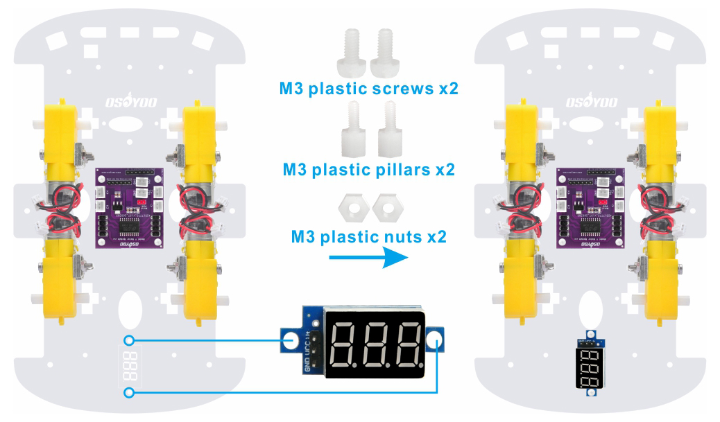
5) Monta il voltmetro sul telaio inferiore usando 2 viti M3 in plastica, distanziali in plastica e dadi in plastica.
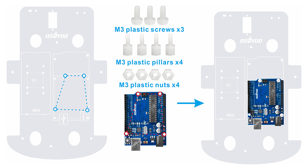
6) Monta la scheda base OSOYOO sul telaio superiore usando 4 viti M3 in plastica, distanziali in plastica e dadi in plastica. (Installa la scheda sul lato con la stampa.)
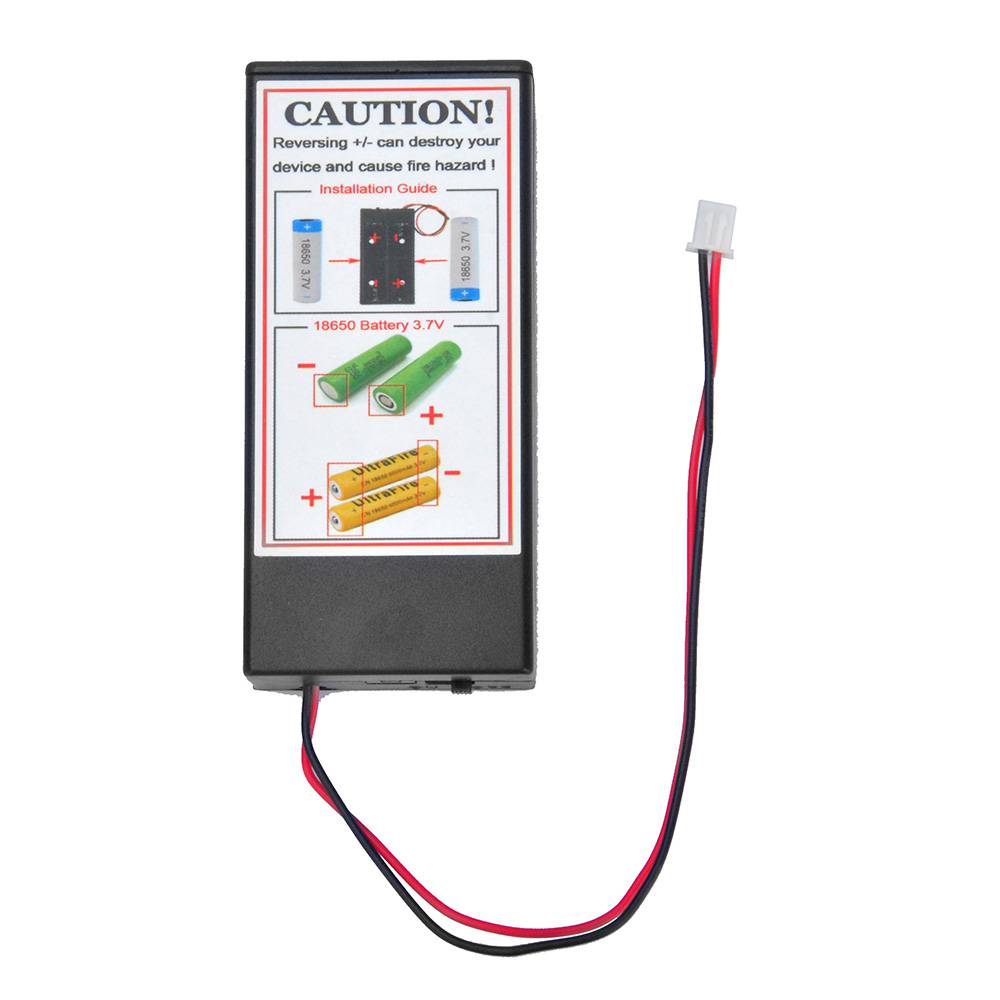
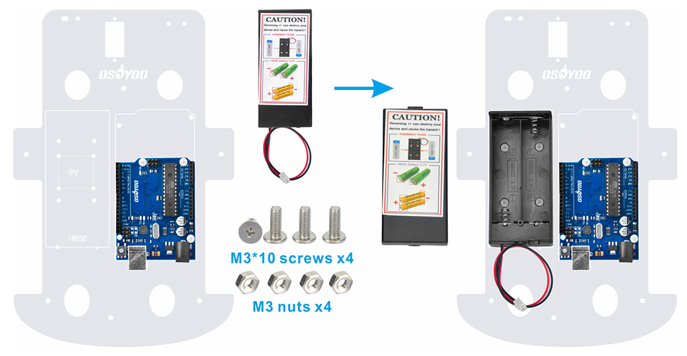
7) Fissa il porta batterie sul telaio superiore usando 4 viti M3*10 e dadi M3.
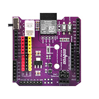
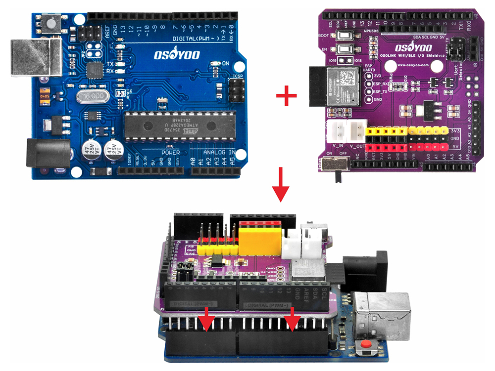
8) Inserisci lo shield OSOYOO WiFi/BLE I/O sulla scheda base OSOYOO.
Collegamento dei componenti
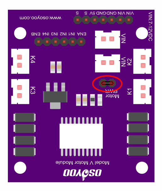
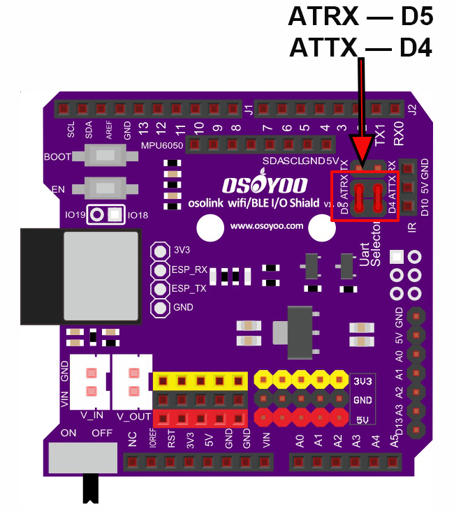
0) Verifica le impostazioni dei jumper cap sul modulo OSOYOO Model V motor shield e sullo shield OSOYOO WiFi/BLE I/O come mostrato di seguito (impostazioni predefinite).
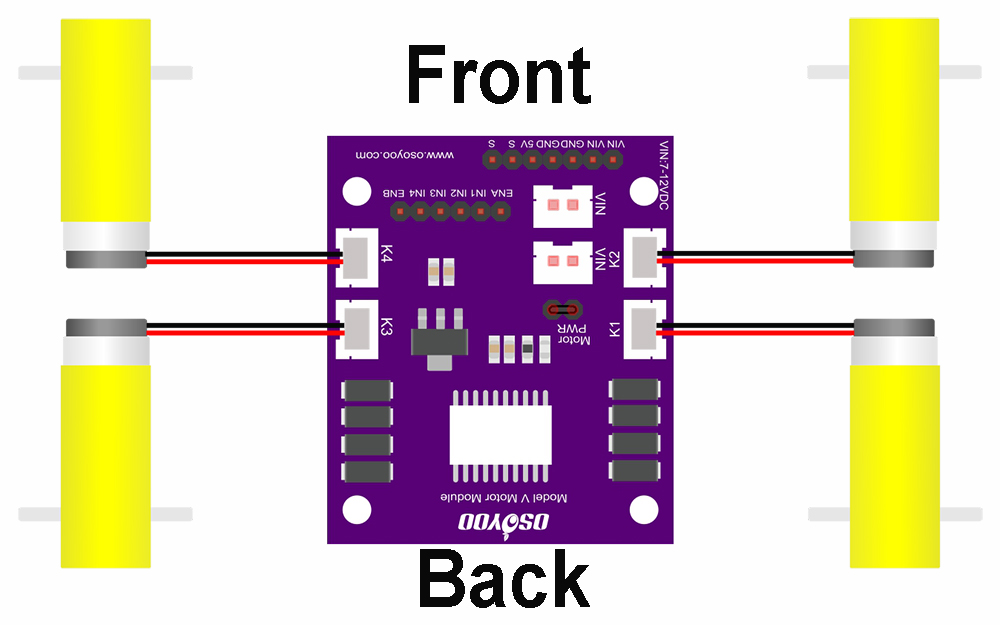
1) Collega i 4 motori ai socket K1–K4 del modulo OSOYOO Model V motor shield come mostrato nel diagramma.
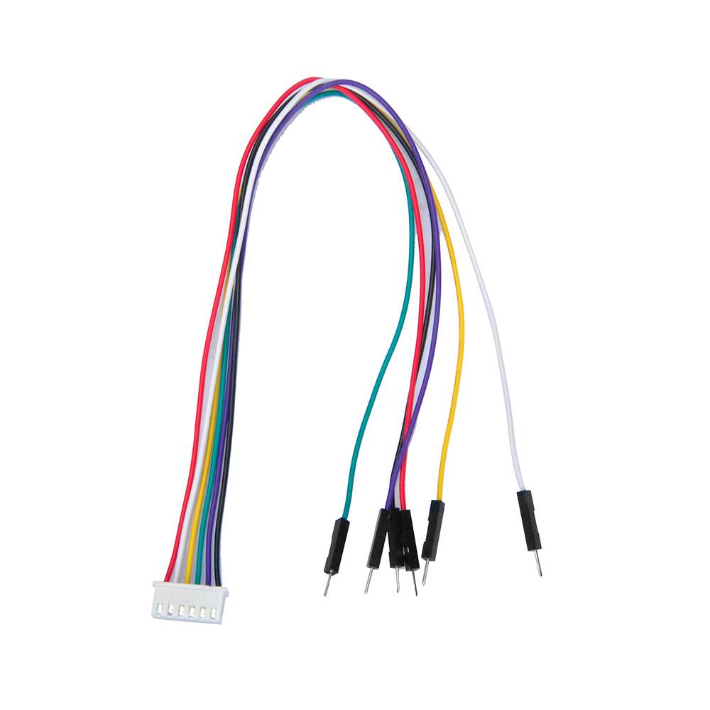
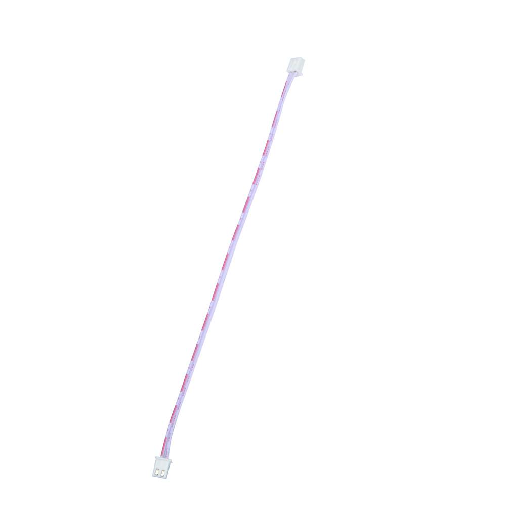
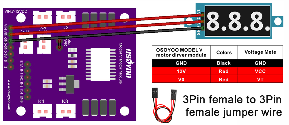
2) Collega il voltmetro al modulo OSOYOO Model V motor shield usando il cavo jumper 3 pin femmina-femmina come mostrato nel diagramma di collegamento.
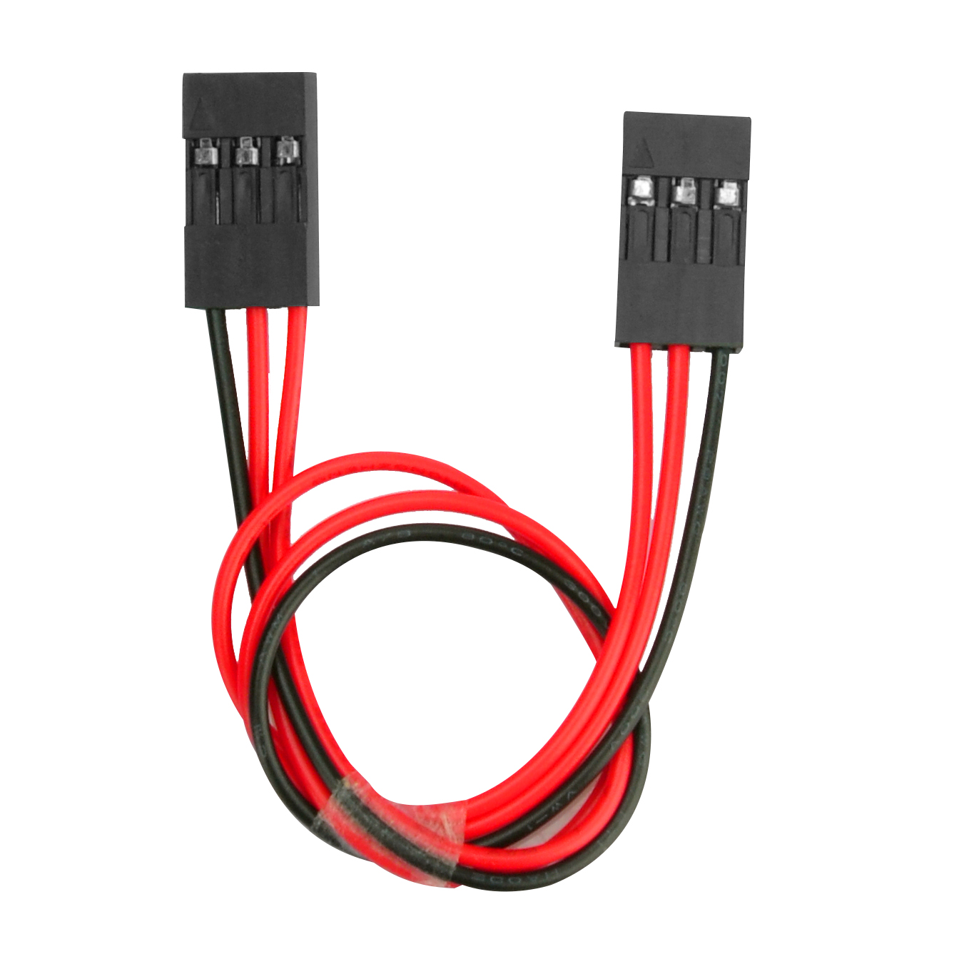
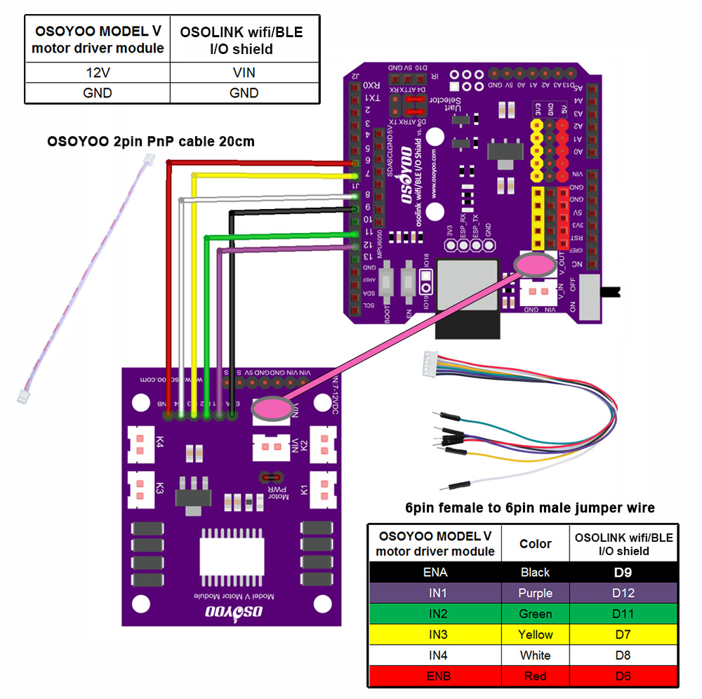
3) Collega i 6 pin di controllo del modulo OSOYOO Model V motor shield a D6, D7, D8, D9, D11, D12 sullo shield OSOYOO WiFi/BLE I/O usando il cavo jumper 6 pin maschio-femmina. Collega anche il socket 12V-GND (VIN) al socket VIN-GND (V_OUT) usando il cavo OSOYOO 2-pin PnP (20 cm), come mostrato nel diagramma. Attenzione:
quando inserisci o rimuovi il connettore a 6 pin dal socket maschio a 6 pin del Model V, tieni il guscio in plastica del connettore. Non estrarre mai il connettore tirando i fili: questo li danneggerebbe.
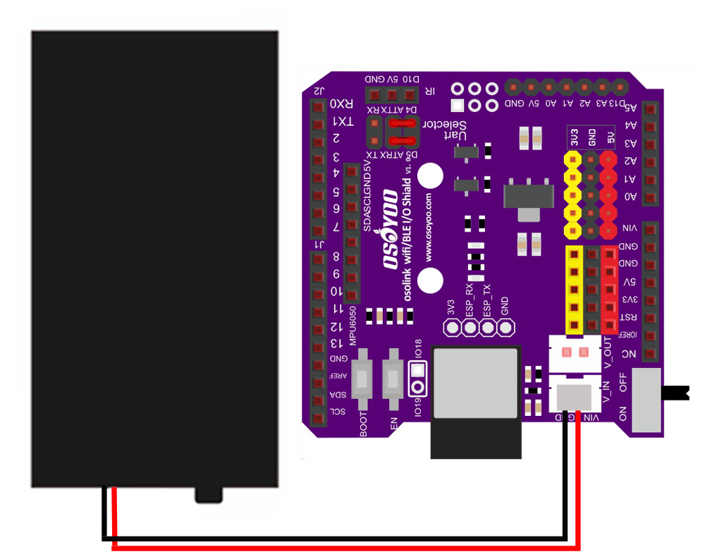
4) Collega il porta batterie al socket VIN-GND (V_IN) dello shield OSOYOO WiFi/BLE I/O come mostrato nel diagramma di collegamento.
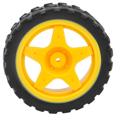
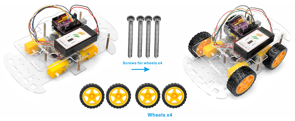
5) Unisci il telaio superiore al telaio inferiore usando cinque distanziali in rame e fissali con 10 viti esagonali M3*10. Poi installa le 4 ruote sui motori. (Allenta le viti delle ruote se qualche ruota non gira liberamente.)
L’assemblaggio hardware è quasi completo. Prima di inserire le batterie 18650, devi caricare il codice di esempio sulla scheda.
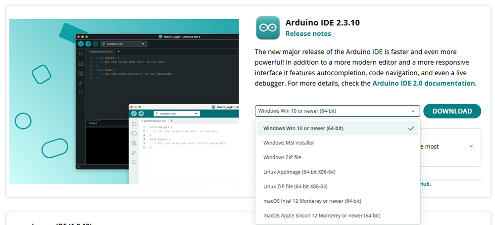
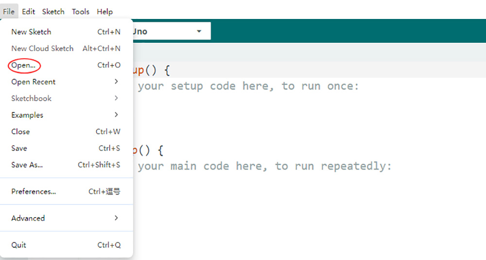
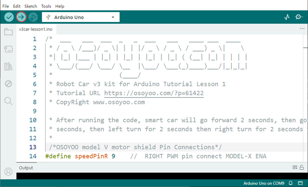
2. Scarica il codice di esempio: Scarica il codice di esempio per la Lezione 1 da qui. Estrai l’archivio per ottenere il file v3car-lesson1.ino nella cartella v3car-lesson1. Apri lo sketch in Arduino IDE.
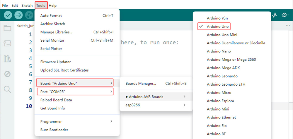
3. Seleziona la scheda e la porta: Collega la scheda base OSOYOO (compatibile con Arduino UNO) al computer tramite un cavo USB. Importante: assicurati che l’interruttore del robot-car sia su OFF e che la batteria sia scollegata prima di collegare la scheda al PC. In Arduino IDE, vai su Strumenti > Scheda e seleziona Arduino Uno. Poi vai su Strumenti > Porta e seleziona la porta seriale corretta. Se non sei sicuro di quale porta scegliere, controlla Gestione dispositivi su Windows.
4. Carica il codice: Fai clic sul pulsante Carica (l’icona con la freccia verso destra) per compilare e caricare lo sketch sulla scheda base OSOYOO.
5Test funzionale e verifica
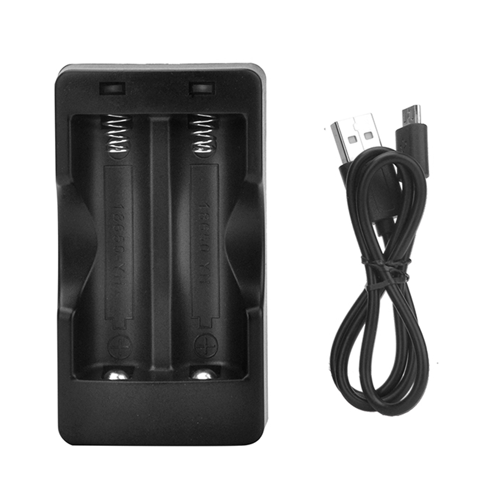
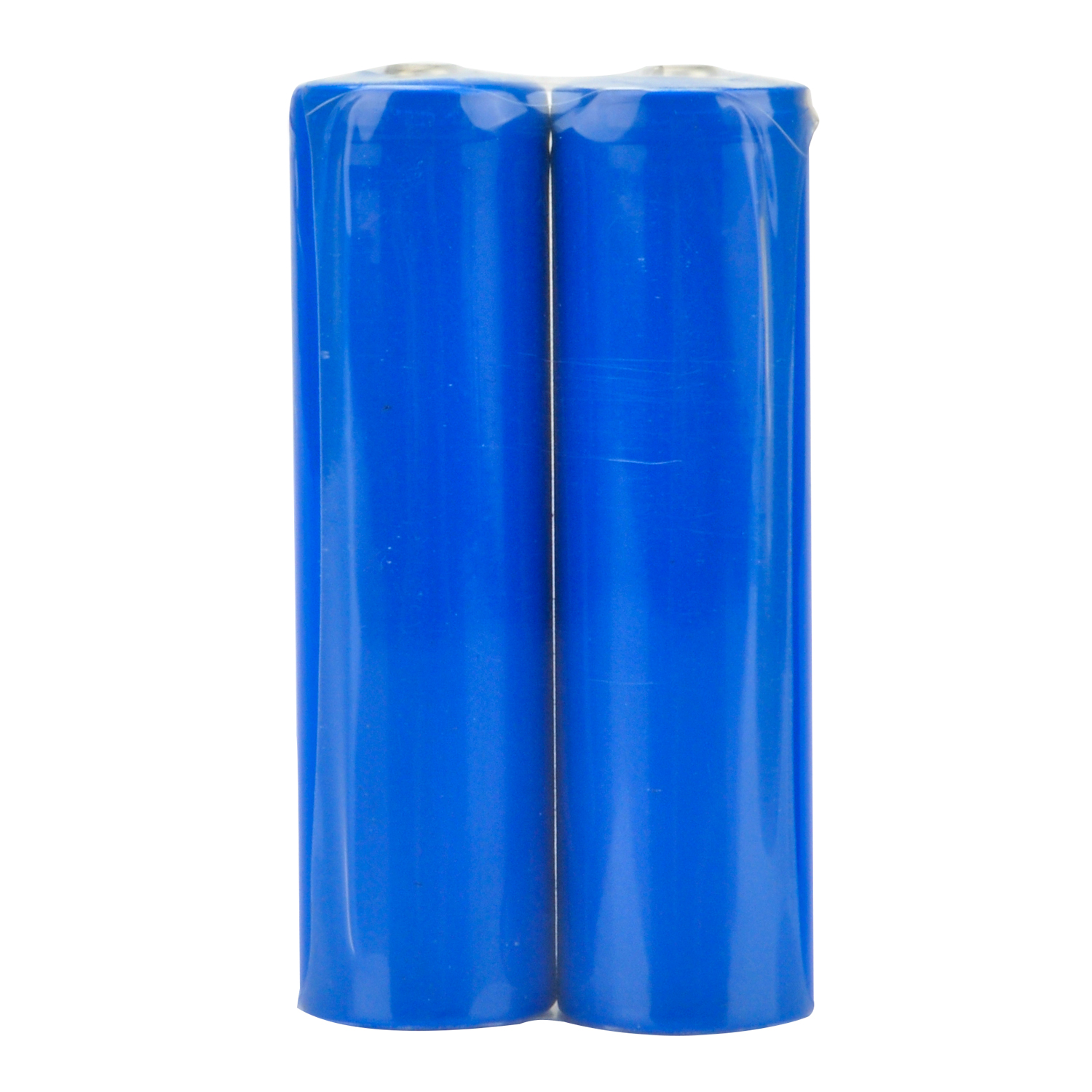
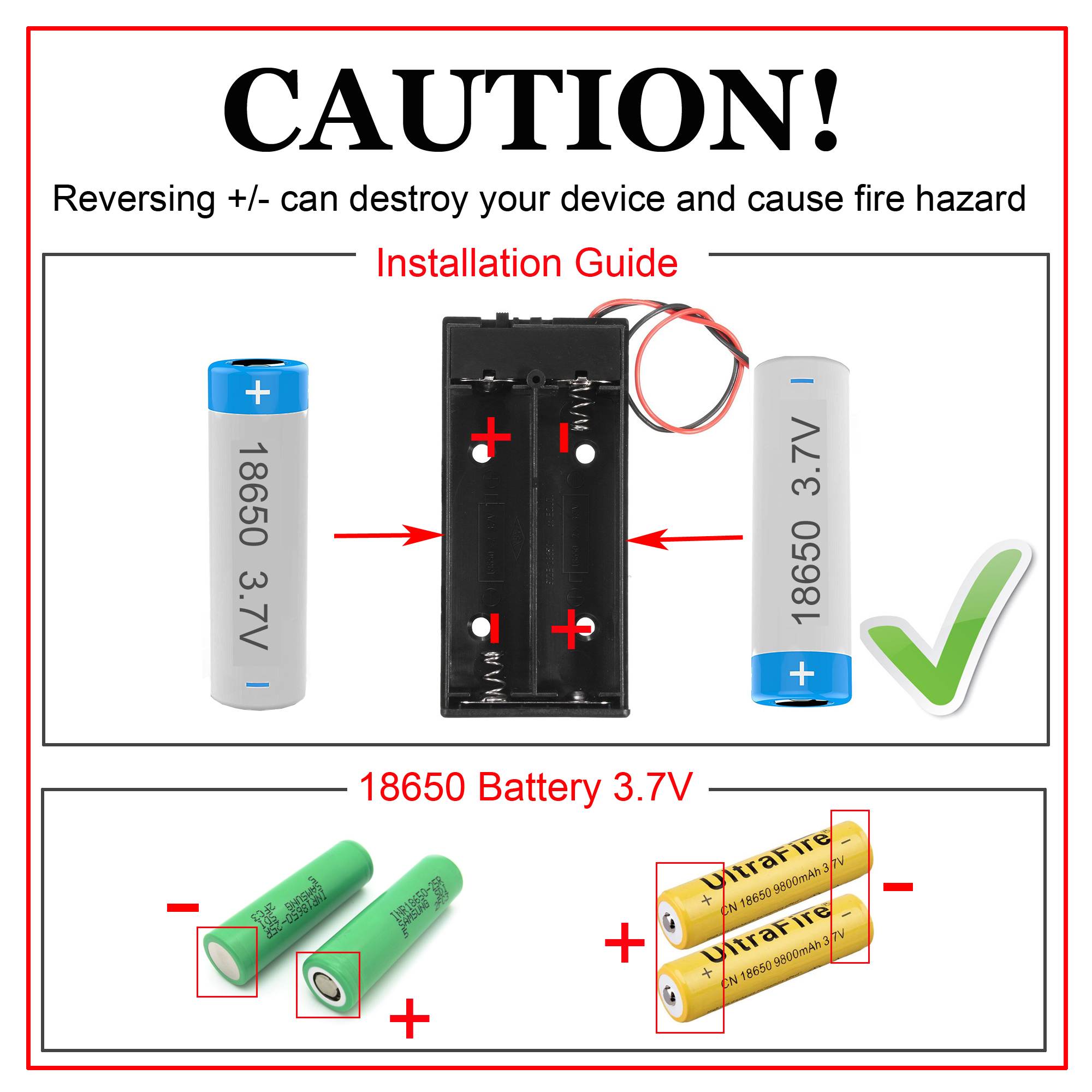
Nota: 1) Consigliamo le batterie 18650: garantiscono un’alimentazione stabile e affidabile al robot-car. 2) Le batterie 18650 usate in queste lezioni sono lunghe circa 65 mm (2,56 pollici) e non hanno un circuito di protezione interno. 3) Controlla l’etichetta del porta batterie e assicurati che la polarità sia corretta. Una polarità invertita può danneggiare il dispositivo e causare rischio di incendio. Dopo aver caricato il codice con successo, scollega la scheda base OSOYOO dal PC. Inserisci le batterie 18650 nel porta batterie rispettando la polarità corretta.
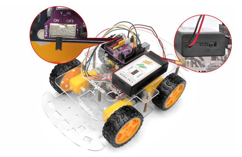
Posiziona il robot-car su una superficie piana e accendi entrambi gli interruttori del porta batterie e dello shield OSOYOO WiFi/BLE I/O. Il robot-car eseguirà una sequenza predefinita di movimenti:
Avanza per 2 secondi
Indietreggia per 2 secondi
Gira a sinistra per 2 secondi
Gira a destra per 2 secondi
Si ferma
Se il robot-car non si comporta come previsto, consulta la sezione di risoluzione dei problemi di seguito.
6Logica di controllo dei motori
Il modulo OSOYOO Model V motor shield usa un circuito a ponte H per controllare la direzione e la velocità dei motori DC. Capire questa logica è fondamentale per una programmazione più avanzata.
Pin di ingresso
Livello logico (IN1/IN2 o IN3/IN4)
Gruppo motori
Direzione
IN1 / IN2
LOW / HIGH
K1 / K2
Indietro
IN3 / IN4
HIGH / LOW
K3 / K4
Avanti
IN3 / IN4
LOW / HIGH
K3 / K4
Indietro
IN1 / IN2
HIGH / LOW
K1 / K2
Avanti
• Controllo della velocità: I pin ENA e ENB, collegati ai pin digitali PWM di Arduino, controllano la velocità dei gruppi di motori K1/K2 e K3/K4. Variando il duty cycle PWM si modifica la tensione effettiva applicata ai motori, regolandone la velocità.
• Mappatura dei pin: ENA, ENB, IN1, IN2, IN3 e IN4 sul motor shield sono collegati ai pin digitali D9, D6, D12, D11, D7 e D8 di Arduino tramite cavi jumper.
7Risoluzione dei problemi
1. Motori fermi / Movimento intermittente:
Alimentazione: Controlla che la tensione della batteria sia superiore a 7,2 V. Ricarica o sostituisci le batterie se necessario. Assicurati che entrambi gli interruttori siano in posizione ON.
Cablaggio: Verifica tutte le connessioni di motori e alimentazione per polarità corretta e buon contatto.
Contatto del motor shield: Assicurati che i 6 pin di controllo del modulo OSOYOO Model V motor shield siano saldamente e correttamente collegati allo shield OSOYOO WiFi/BLE I/O, con tutti i pin allineati. Se necessario, sostituisci il cavo jumper a 6 pin con sei cavi jumper singoli femmina-femmina.
Verifica del motore: Se un solo motore non funziona, sostituiscilo con un motore funzionante per capire se il problema è nel motore stesso.
2. Direzione di movimento errata:
Se il robot si muove nella direzione sbagliata, controlla che i fili rosso e nero dei motori siano saldati correttamente su tutti i motori e assicurati che i 6 pin di controllo del modulo OSOYOO Model V motor shield siano collegati correttamente allo shield OSOYOO WiFi/BLE I/O.
3. Problemi di connessione con Arduino IDE:
Installazione del driver: Assicurati che i driver USB-seriale corretti per la tua scheda Arduino siano installati.
Selezione della porta: Conferma che la porta COM corretta sia selezionata in Arduino IDE. Su Windows, puoi verificare in Gestione dispositivi sotto “Porte (COM e LPT)”.
Se nessuna delle soluzioni precedenti risolve il problema, scrivici a [email protected] o lascia un commento in fondo a questo tutorial. Il nostro team di supporto tecnico sarà lieto di aiutarti.