- OSOYOO ESP8266 Wifi Module
- OSOYOO W5100 Ethernet IoT learning Kit
- OSOYOO Wifi IoT Learning Kit
- Smart House V2.0 Blynk Control
- Blynk IoT Learning Kit
- LoRa Related
- NodeMCU IoT Kit
- Smart Home Iot Kit
- Smart Home V2.0 UDP APP control
- Project for Raspberry Pi
- FlexiRover Robot Car for Raspberry Pi/Arduino
- IOT kit for raspberry Pi
- Mecanum Wheel Car
- OSOYOO basic kit for Raspberry pi zero
- OSOYOO Robot Car V1 for Raspberry Pi
- OSOYOO Robot Car V2 for Raspberry Pi
- OSOYOO Starter Kit V1 for Raspberry Pi
- OSOYOO Starter Kit V2 for Raspberry Pi
- Screen for Raspberry Pi
- Tank Car for Raspberry Pi
- OSOYOO V4.0 Robot Car for Raspberry Pi
- LilyPad Sewing electronic Kit
- NodeMCU Garden Watering Kit
- OSOYOO 3D Printer Kit
- OSOYOO Advanced Hardware Programming Learning Kit
- OSOYOO Basic Programming Learning Kit
- OSOYOO Cayenne IOT Learning Kit
- OSOYOO Graphical Programming Kit
- Osoyoo Hardware Programming Starter Kit
- OSOYOO IoT Smarthome Kit V0.1
- OSOYOO PNP Programming Learning Kit
- OSOYOO RFID Programming Learning Kit
- Osoyoo Sensor Modules Kit
- OSOYOO Smart Home IoT Kit
- OSOYOO Ultimate Hardware Programming kit
- OSOYOO v3 advanced learning kits
- 16+1 Sensor kit
- Smart Car Kit
- Balance car kit
- Blue Mecanum Wheel Robotic for Arduino Mega2560
- Blue Mecanum Wheel Robotic for Raspberry Pi
- M1.0 Mecanum Wheel Metal Chassis Robotic
- M2.0 Mecanum Wheel Metal Chassis Robotic
- Mars Explorer Mecanum Wheel Robot Kit
- Tank Car Kit V1.0
- Tank Car Kit V2.0
- 2WD Robot Car Starter Kit
- Model-3 V2.0 Robot Car
- OSOYOO Model-3 Robot Learning Kit
- OSOYOO Model-T Robot Car
- OSOYOO Robot Car Starter Kit Tutorial
- OSOYOO Servo Steering Car V3.0 for Arduino MEGA2560
- P3 Servo Steering Robot Car
- SG90 Servo Steering Robot Car
- V2.0 Robot Car kit
- V2.1 Robot car kit
- Sewing eletronic widgets
- Breadboard
- Buzzer
- LED
- Resistor
- Screen
- Sensors
- Temperature sensor
- USB cable
- Wires
- IO-breakout-board-for-ardino-UNO
- IO-breakout-board-for-arduino-nano
- IO-breakout-board-for-arduino-pro-micro
- IO-breakout-board-for-esp32&esp8266
- IO-breakout-board-for-raspberry-pico
- Nano for arduino
- LTG-Nano for Arduino
- Motor driver board
- NodeMCU
- Pro micro for Arduino
- PWM HAT for Rapberry Pi


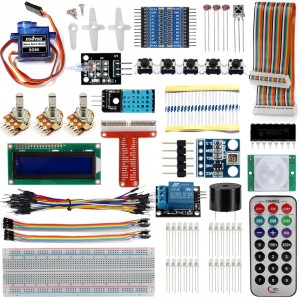

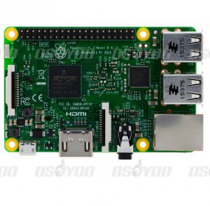


There’s some info apparently missing at the end of the first paragraph on the page. The last sentence is truncated. It reads, “In order to best protect your pi 3….”
What are we supposed to do to best protect our pi 3?
thx for your notice.
In order to best protect your pi 3, you’better to connect the component with 3.3V GPIO (Note: For some sample projects, you need to connect 5V GPIO, pls follow our sample project to test your component.)
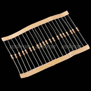
Why did my kit contain 200ohm resistors instead of 220ohm that the projects call for?
We have changed the package of the Resistors.
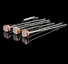
Hi, do you have the datasheet for the photo resistor or its code? Thanks
Do you mean you need resistor color code: https://osoyoo.com/2014/12/08/how-to-read-resistor-color-code/
No, I mean the photoresistor used in this project
https://osoyoo.com/2016/12/16/raspberrypi-photoresistor/
I would like to convert the readings to actual lux.
Thanks
Type: 5516,
Maximum Voltage: 100 (VDC),
Maximum Power:90 (mW),
Spectral Peak:540(nm),
Light Resistance (10Lux):5~10(kOhm),
Dark Resistance:0.2(MQ / MOhm)
Sensitivity:0.6(min)
Response Time (rose and Drop):30 and 40(ms)
Thanks!
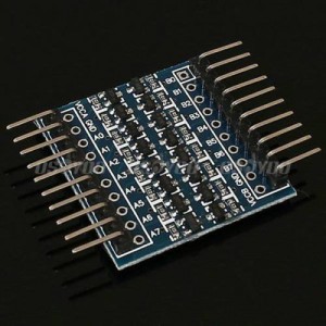
Raspberry Pi/Arduino 8-チャンネル TTLロジックレベル変換器の使い方を教えていただけないでしょうか?
サンプルプロジェクトも無く行き詰っています。
・これは双方向ではなく、一方向(A to B)の変換のみであっていますでしょうか?
・変換機には、VCCAが2ピン、VCCBが2ピン、GNDが4ピン存在します。
これは全て接続する必要がありますか?
sorry, i don’t know how to write Japanese. I use English to reply your question.
1)The TTL Logic Level Converter showed in this kit is bi-directional. That means you can convert both from 3.3V signal to 5V signal and reversely from 5v to 3.3V
2)please connect VCCA to 3.3V and VCCB to 5V, all A pins connect 3.3V devices and B pins to 5V devices.
Hope this is clear
日本語で説明します:
1)このキットでのTTLロジックレベル変換器は双方向の物です。3.3vから5vへ変更できるし、5vから3.3vへ変更も大丈夫です。
2)VCCAと3.3V、VCCBと5Vを接続してください。すべてのAピンと3.3V設備を接続し、すべてのBピンと5V設備を接続してくださいませ。
丁寧なご回答ありがとうございました。
説明のとおり接続したところ、3.3Vから5Vへ変換できることが確認できました。
勉強になりました。