RFID(英: radio frequency identifier)とは、ID情報を埋め込んだRFタグから、電磁界や電波などを用いた近距離(周波数帯によって数cm~数m)の無線通信によって情報をやりとりするもの、および技術全般を指します。 従来のRFタグは、複数の電子素子が乗った回路基板で構成されていたが、近年、小さなワンチップのIC (集積回路)で実現できるようになってきました。 これはICタグと呼ばれ、そのサイズからゴマ粒チップと呼ばれることもあります。
普段、RFIDは2つの部分、RFID キー と RFID リーダー(センサー)があります。 このプロジェクトでは、RFID リーダーを使って、RFID キー にあるID情報を獲得します。
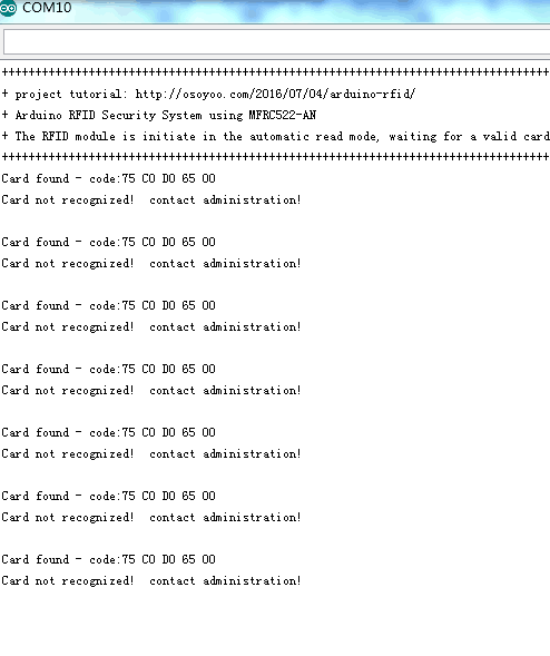
獲得したのID情報と記録したの情報が間に合わない場合、レッドLED点灯し、LCDで”Card not recognized! contact admin”を表示して、Arduino IDEのserial windowで”Card found – code: ** ** ** ** ** ” を表示します。 ‘** ** ** ** **’は5バイトのヘックスIDです。
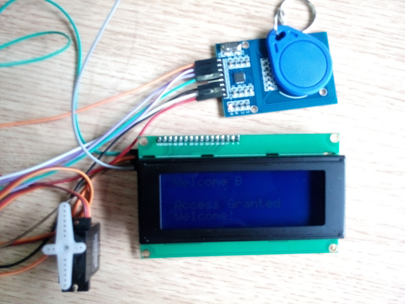
獲得したのID情報と記録したの情報が間に合う場合、 マイクロサーボは180度回し(ドアの開けを模倣する)、グリーンLEDを点灯し、 LCDで”ID Found!… Welcome X!”と表示します。
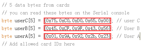
鍵のヘックスIDコードはArduino IDEのserial windowで獲得できます。鍵のヘックスIDコードを獲得したら、「RFID_Simples_V3_English.ino」ファイルで line 25, 26, 27 の数値を取り替えしてくださいませ。
2 . 必要なデバイス
Arduino UNO R3ボード x 1 ;
マイクロサーボ x 1;
RFID 鍵とレシーバー;
圧電ブザー x 1
220 ohm 抵抗 x 2;
レッド LED x 1;
グリーン LED x 1;
I2C LCD x 1;
ブレッドボードとジャンパワイヤ;
3) 回路の組み立て(画像をクリックして拡大イメージを表示)

RFID センサーpinとArduinoボードの接続方法:
| RFID センサー |
Arduino |
| Reset |
D5 |
| SDA |
D10 |
| MOSI |
D11 |
| MISO |
D12 |
| SCK |
D13 |
| GND |
GROUND |
| 3.3v |
3.3v |
ArduinoとLCD(i2c) pin の接続方法:
| I2C LCD |
Arduino |
| SDA |
A4 |
| SCL |
A5 |
| VCC |
5V |
| GND |
GND |
ArduinoとLED、マイクロサーボの接続方法:
| device |
Arduino |
| Red LED long leg |
D3 |
| Green LED long leg |
D2 |
| servo signal(orange line) |
D9 |
| servo VCC(red line) |
5v |
| servo GND(brown line) |
GND |
| Buzz VCC |
D8 |
4)ソフトウエアのインストール
https://osoyoo.com/driver/ArduinoRFID.rarをダウンロードして、rarファイルを解凍して、”ArduinoRFID”フォルダに”library”フォルダがあります。”library”フォルダですべてのフォルダをArduino IDE\libraryに導入してくださいませ。
5) – LCDのI2Cのアドレスを探す
常識ですが、デバイスはコマンドの受信やメッセージを送信のため、I2C アドレスがありますね。 Arduino Uno ボード の場合、普段は0x27というアドレスがありますが、 0x37,0x24 ….,などに変更した事もあります。そのため、I2C アドレス探しましょう~
ic2_scannerというファイルをダウンロードして、 Arduino IDEにロードしてくださいませ。Arduino IDEの操作画面で「Tools」-「serial monitor」を開いて、I2Cアドレスを表示できると思います。
普段は0x27ですが、異なるの場合も御座います。

次のstepに必要ですので、表示されるアドレスを記録してくださいませ。
5)プロジェクトを動作する
“ArduinoRFID”フォルダで「RFID_Simples_V3_English」フォルダがあります、「RFID_Simples_V3_English.ino」 ファイルをArduino IDEに開けて、ファイルでのI2C addressを先ほど記録したの数値を変更して下さい。

コードをArduino IDEにロードしてくださいませ。ロード完了したら、serial windowで下記のように、表示します。(画像をクリックして拡大イメージを表示)

RFID 鍵をセンサーにタッチしたら、下記のように表示します(画像をクリックして拡大イメージを表示):

次のSETPに必要ですので、上記の実際のcard codeを記録してくださいませ。
8)サンプルコードでのcard codeを先ほど記録したの数量を切り替えして下さい。(例: card code: 75 C0 D0 65 00,
サンプルコードに 0x75,0xC0,0xD0,0x65,0x00を編集して下さい。):

9)有効なRFID 鍵をセンサーとタッチしたら、ArduinoIDEのSerial Monitor窓に下記のように、表示します:

マイクロサーボは180度回して、ブザー1回鳴り、グリーンLEDを点灯します。


Sir good day about this project i want to make it work when the card is still in and card reader when i remove the card the door locks again . how to change the code ?thanks
our sample code actually can meet your requirment.When you tap the key into RFID sensor, the lock(we use servo to immitate lock) will open. After 3 seconds, the lock will automatically close. In our project Arduino file RFID_simples_V3_English.ino line 135 to 137, you can change the parameter in function doorLock.write() to control the lock open or close, you can also change the delay time in line 136.
Hello
can you help me with these
1- How can I change the login sound? I want regular sound not a music
2- I want to change the startup screen “RFID Test by etc”
3- I want to change the user “Welcome A” to “Welcome (any name)”
4- can I add a 4*4 keybad?
last thing
5- I don’t want to close the door automatically I want to scan the opening card to close it can I do that?
1. It can’t change the sound in this code
2. You can change the line 333 to 380 code “RFID_Simples_V3_English”
3. You can try to change the codes about User A
4. You need to change the code and set the graph
5. In our project, When you tap the key into RFID sensor, the lock(we use servo to immitate lock) will open. After 3 seconds, the lock will automatically close. In our project Arduino file RFID_simples_V3_English.ino line 135 to 137, you can change the parameter in function doorLock.write() to control the lock open or close, you can also change the delay time in line 136
thank you very much
I will start fixing that right now and I will give you my upadate
It’s my pleasure.
Hi again
I am trying to add the keypad
but it’s not working
can you help me with the code
I want to open the door(servo) by using the RFID and Password
I connected the keypad as the diagram show and I include the keypad
and library but i got this
Arduino: 1.8.2 (Windows 10), Board: “Arduino/Genuino Uno”
C:\Users\Alienware\Downloads\Compressed\ArduinoRFID\RFID_Simples_V3_English\RFID_Simples_V3_English.ino:19:20: fatal error: Keypad.h: No such file or directory
#include
^
compilation terminated.
Multiple libraries were found for “SPI.h”
Used: C:\Program Files (x86)\Arduino\hardware\arduino\avr\libraries\SPI
Not used: C:\Program Files (x86)\Arduino\libraries\SPI
Multiple libraries were found for “Wire.h”
Used: C:\Program Files (x86)\Arduino\hardware\arduino\avr\libraries\Wire
Not used: C:\Program Files (x86)\Arduino\libraries\Wire
exit status 1
Error compiling for board Arduino/Genuino Uno.
Invalid library found in C:\Program Files (x86)\Arduino\libraries\examples: C:\Program Files (x86)\Arduino\libraries\examples
Invalid library found in C:\Program Files (x86)\Arduino\libraries\examples: C:\Program Files (x86)\Arduino\libraries\examples
This report would have more information with
“Show verbose output during compilation”
option enabled in File -> Preferences.
I’m sorry I don’t test this tutorial with keypad, but you can try the tutorial about keypad: https://osoyoo.com/2016/07/21/4x4keypad/
can I add the keypad code to the code above?
if yes how can I fix keypad code to make it working with the codes above
Please try to compile two part code together and change some code and have a try
Hi, I’ve checked four times that the RFID sensor is wired correctly, but it still isn’t reading the card or tag. How do I troubleshoot that? Thanks
Do you solder the pin on the RFID sensor?
i also have soldered the pins to rfid sensor. good clen joins. no dry joints. still not working. just D1 led on rfid sensor is permantly lit.
Please help. !!
Are you willing to try to the tutorial: https://osoyoo.com/2017/09/11/arduino-lesson-rfid-rc522/?
This tutorial is just for RFID sensor. Please confirm whether the sensor works or not.
Hi. Thanks for the guide but this is soo far from accurate. the picture layout at the top (47.jpg) doesn’t even match and is such a low resolution i cant see the pins..
Is there a more comprehensive guide please? or if anybody has got this to work, can you share a close up pictures please?? and codes too please?
i really want buzzer, leds, lcd servo and rfid to work, but with the pin out and instructions above
i only have D1 led lit.
The little servo is making a very quiet hum sound and resisting being turned.
When rebooting, the lcd comes on and then off after a few seconds
the code is saying it’s waiting for Valid card in the com port monitor window.
PLEASE PLEASE can you share better pictures of the layout of working project. 🙁
Hi, cheers for the tutorial everything is working fine except that nothing is appearing on the LCD Display. It lights up when I hold a card to the RFID reader but for what ever reason no text is appearing. Do I need to add something to the code for the text to appear? If so please advise.
Please adjust the backlight of the LCD.
Do you check the I2C address of your LCD and change I2C address when you run the project?
can replace with lcd 16×2 and MFRC 522