*編集中********
米国から購入 英国から購入 DEから購入 ITから購入 FRから購入 ESから購入 JPから購入

*目的

このレッスンでは、ボタンスイッチモジュールを使用して、アルドゥイーノグラフィックプログラミングテクノロジーを介してLEDをオン/オフにする方法を示します。

LEDとスイッチモジュールの両方がOSOYOOマジックI / Oシールドに接続されます。ここで、「I / O」とはINPUTとOUTPUTを指します。OSOYOO Magic I / O Shieldは、センサー、アクチュエーター、ロボットカーの制御ポートをアルドゥイーノI / Oピンに簡単に接続するために使用できる拡張ボードです。

LEDモジュールをシールドのD8ポートに接続し、スイッチモジュールをシールドのD2ポートに接続します。アルドゥイーノD8が制御LEDに信号を送信する出力ポートになることを伝えます。D2は、スイッチボタンから入力信号を取得するINPUTポートです。

すると、アルドゥイーノグラフィック・レ技術をて、ボタン・押し・箱を押してLEDをオン/オフする方法を紹介します。

LEDと入力・入力のOSYOO ​​Magic I / Oシールドになりします。ここでます「I / O」とは、入力(INPUT)と入力(OUTPUT)のことです。OSOYOOMagicI/ Oシールドは、レーザーや継ー、ロボットカーの反射灯卓を、アルドゥイーノのI / Oピンにいに積分可能入力ボードです。

LEDBOXをシールドのD8ポートに収、ポートコネクタをシールドのD2ポートにあります。アルドゥイーノがD8がLEDを測定するの声を入力ポートポート、D2ポートボタンからの入力をしたポートになります。


*チョダン

ボタンスイッチモジュールは信号発生器です。ボタンを押すとSIGピンがHIGH電圧信号を生成し、ボタンを離すとSIGピンがLOW電圧信号を生成します。

LEDモジュールはSIGピンがHIGH電圧信号を取得するとオンになり、SIGピンがLOW電圧信号を取得するとオフになります。

ボタン押しボタンは、信号発生です。ホルが押収と、SIGピンからHIGH電圧信号を入力し、ボタンが離倒し、SIGピンはLOW電圧信号になります。LEDKは、SIGピンのHIGH電圧信号を入力してオンになり、SIGピンがLOW電圧信号を入力してオフになります。

*作り方

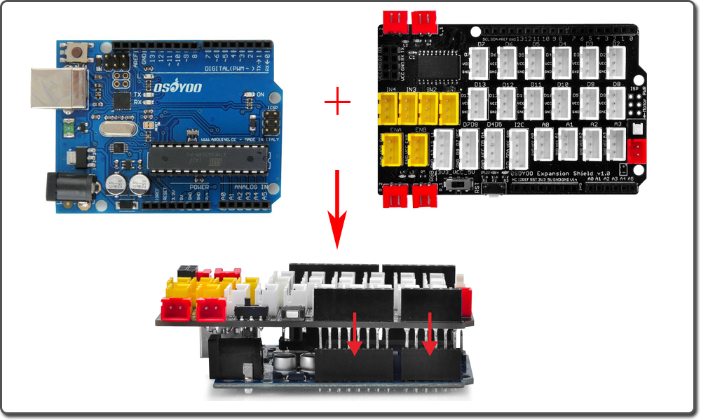
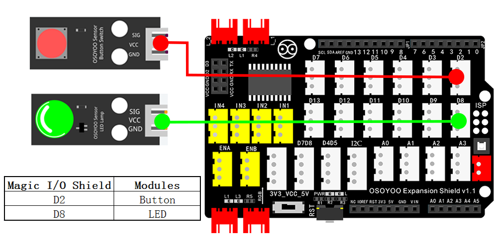
First, please plug Osoyoo Magic I/O shield into UNO board. Then connect the Button and LED module to the D2 and D8 port of the Magic I/O shield with a 3-pin PNP cable as below:

まず、Osoyoo Magic I/OシールドをUNOボードに接続してください。次に、スイッチボタンとLEDモジュールを、Magic I/OシールドのそれぞれD2ポートとD8ポートに、以下のように3ピンPNPケーブルで接続します。


Notice: Shut off your battery or Unplug your power adapter when upload sketch code to アルドゥイーノ.

*注意:。アルドゥイーノにスケッチコードをアップロードする際は、バッテリーをオフにするか、電源アダプターを抜いてください。

You can download the code directly, then click “Open” in Mixly to choose the code you download:

Download the Code

Or you can do as following operations:

コードを直接ダウンロードし、Mixlyの “Open “をクリックして、ダウンロードしたコードを選択することができます:コードのダウンロード または、以下の操作を行うことができます:


After above circuit installation is completed, connect the アルドゥイーノboard to your computer using the USB cable. The green power LED (labelled PWR) will turn on.
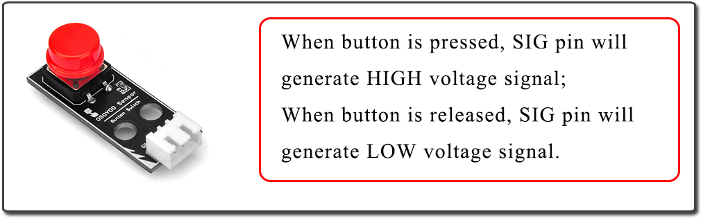
We have learnt how to make an LED blink in last lesson. So in this one we will add a button to control the LED on/off.
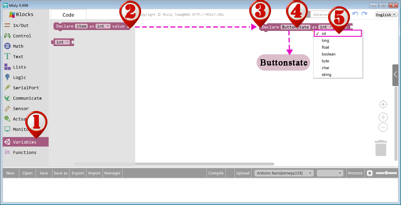
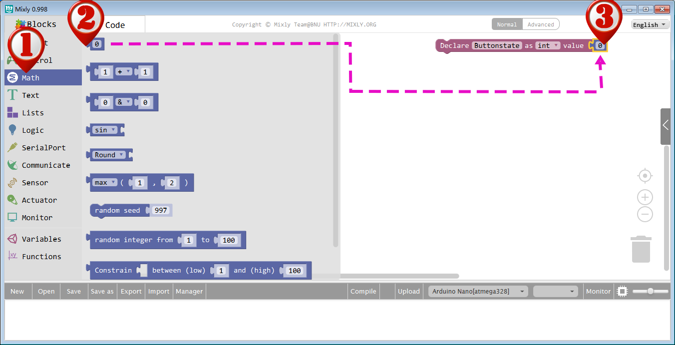
First, we need to declare a variable to show the Buttons state. Drag out a Declare block in Variables category.

上記の回路のインストールが完了したら、アルドゥイーノボードをUSBケーブルでコンピュータに接続します。緑の電源LED(PWRと表示されている)が点灯します。前回のレッスンでLEDを点滅させる方法を学びました。まず、ボタンの状態を表す変数を宣言する必要があります。VariablesカテゴリにDeclareブロックをドラッグアウトします。

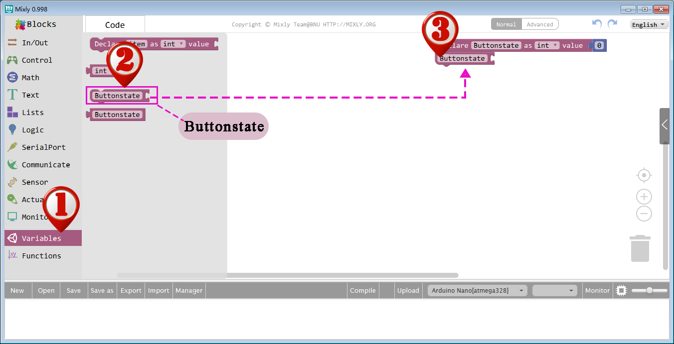
Name this variable to ”Buttonstate”, and select the type to int.

ここでは変数名を”Bttonstate”でint型を選択します行います。

To assign 0 to Buttonstate initially, drag out the “0” block(the first block) in Math, and add it behind the Buttonstate. The value in the block can be changed, here we use its default value “0”.

最初にButtonstateにゼロ(0)を割り当てるには、Mathで「0」ブロック(最初のブロック)をドラッグアウトして、Buttonstateの後ろのValuneに追加します。このブロックの値は変更可能ですが、ここではデフォルト値の「0」を使用します。

Now we need find some way to get value from D2 port and give it to Buttonstate variable. To do this, please click Variables category again, drag a Buttonstate block to blank area as follow picture:

次に、D2ポートから値を読み取り、”Buttonstate”変数に渡す方法を考えます。そのためには、変数カテゴリをクリックして、”Buttonstate”ブロックを下図のように空白エリアにドラッグします。

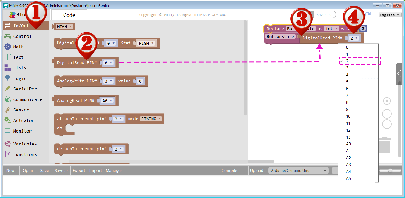
Then go to In/Out category, drag a digitalRead block and drop it behind the Buttonstate block and combine them together. Now you need set the PIN# to 2 which means you will assign input signal from PIN# 2 to Buttonstate variable.

次に、In/Outカテゴリに移動し、digitalReadブロックをドラッグして”Buttonstate”ブロックの後ろにドロップし、それらを結合します。ここで、PIN#を2に設定する必要があります。つまり、PIN#2からの入力信号をButtonstate変数に割り当てることになります。

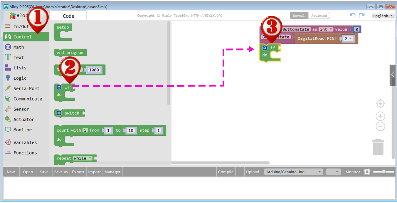
Now let’s explain our control logic to アルドゥイーノ. We want to turn on LED when we press button and turn off LED when button is released. Let’s use Graphic Blocks to give our logic to アルドゥイーノ:

それでは、アルドゥイーノへの制御ロジックを説明します。ボタンを押すとLEDが点灯し、ボタンを離すとLEDが消灯するようにしたいのです。

First , we drag an if do block in Control category right below Buttonstate block as following picture

まず、Buttonstateブロックの下にあるControlカテゴリの”if do”ブロックをドラッグします。

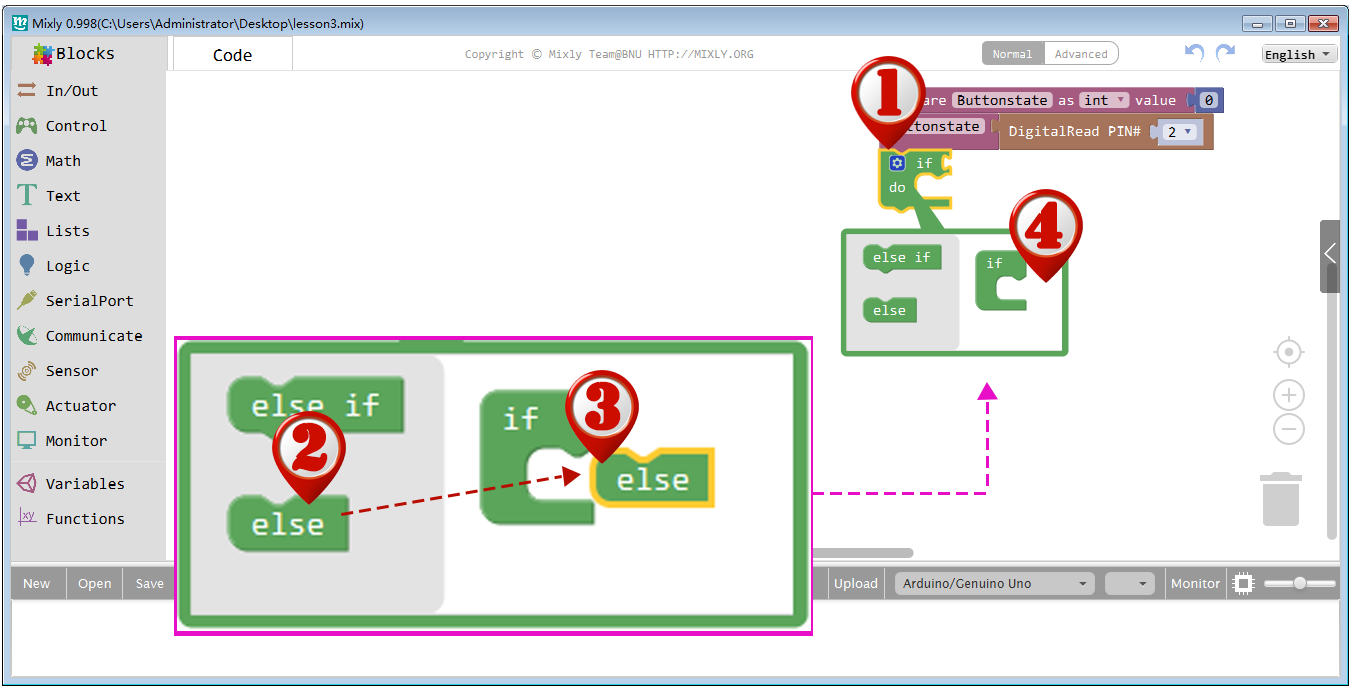
We also need add a else sub-block to this if do block. To do this, just click the setting icon inside if do block, drag out an else sub-block and connect it to if block, then Click setting again to turn off the setting window.

また、この”if do”ブロックに”else”サブブロックを追加する必要があります。これを行うには、”if do”ブロック内の設定アイコンをクリックし、”else”サブブロックをドラッグアウトして”if”ブロックに接続した後、もう一度設定をクリックして設定ウィンドウをオフにします。


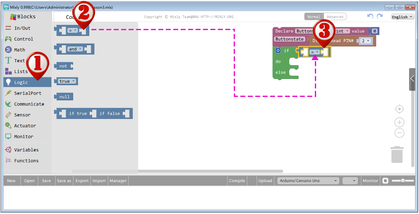
Next, we should add the condition logic block into above if do else block. To do this, Drag out the first “=” block in Logic category, and drop it to the right side of if slot as showed below.

次に、上記の”if do else”ブロックに条件ロジックブロックを追加します。そのためには、Logicカテゴリの最初の「=」ブロックをドラッグして、下図のようにifスロットの右端にドロップします。

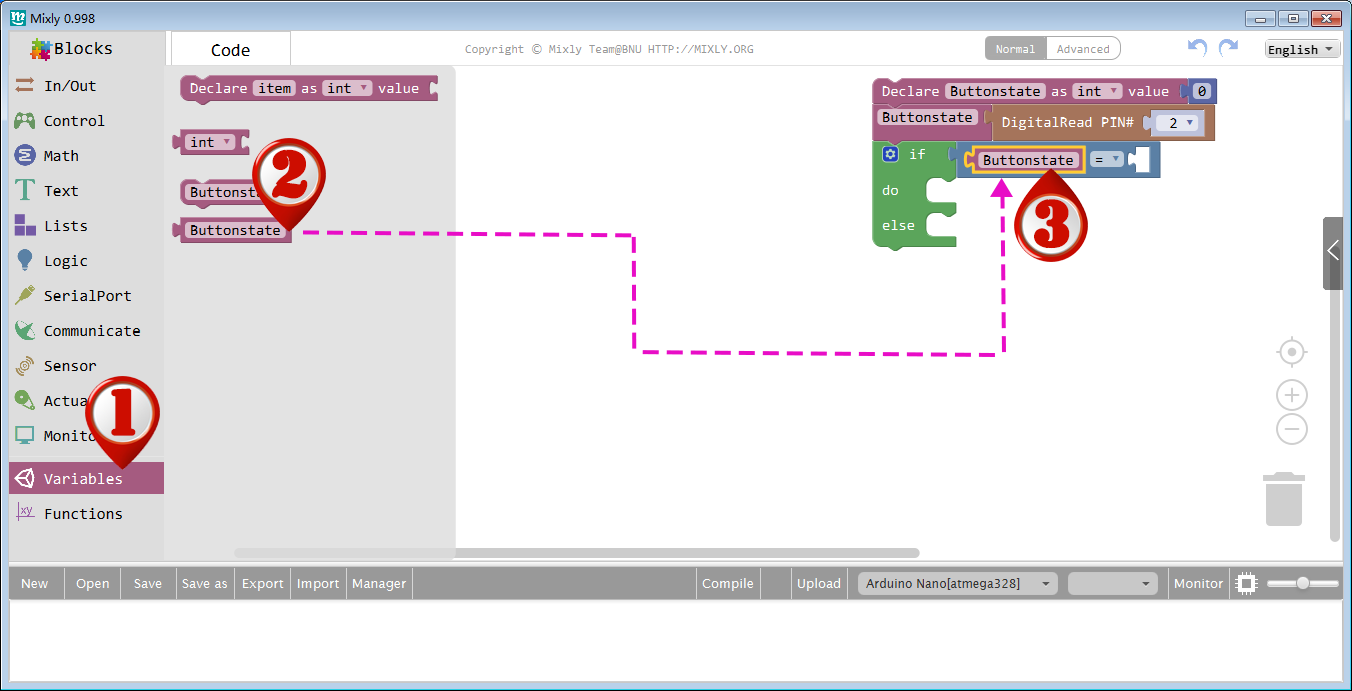
Drag out a Buttonstate block from Variables category, and drop it to the left slot of = block as showed below.

変数カテゴリーから”Buttonstate”ブロックをドラッグして、下図のように「=」ブロックの左スロットにドロップします。

Drag out the HIGH block in In/Out section, and drop it to the right slot of the “=” block as showed below.

in/Outセクションの”HIGH”ブロックをドラッグアウトして、下図のように”=”ブロックの右スロットにドロップします。

Now, the if else logic structure is completed.

これで、if elseの論理構成が完成しました。

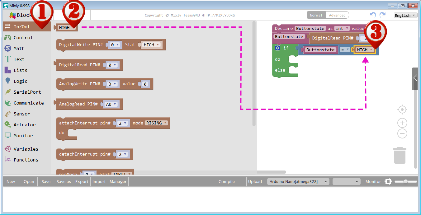
Next we need to set the action when Buttonstate is in HIGH situations.
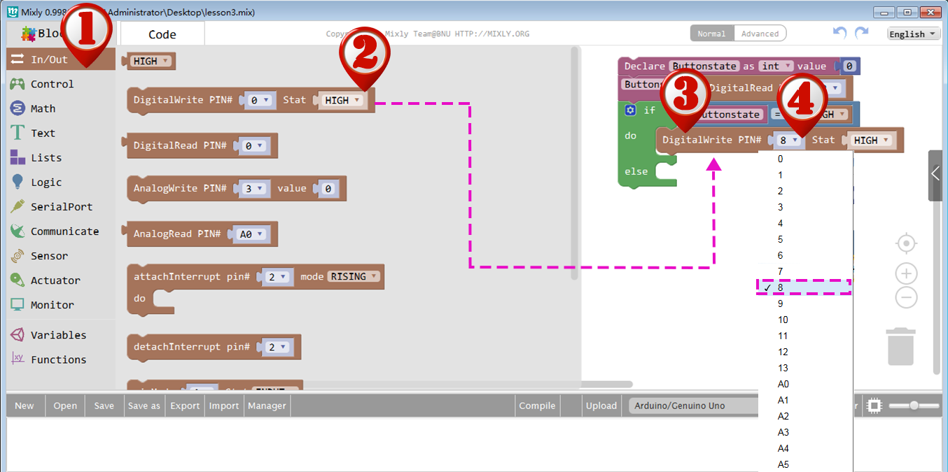
Drag a DigitalWrite block from In/Out section and drop it on the right side of do slot, then set PIN# to 8 and Stat value to HIGH as showed below:
次に、”Buttonstate”が”HIGH”の時の動作を設定します。In/Outセクションから”DigitalWrite”ブロックをドラッグして、”do”スロットの右側にドロップし、下図のようにPIN#を8に、Stat値を”HIGH”に設定します。

Next we need to set the action when Buttonstate is in LOW situations.
Drag another DigitalWrite block from In/Out section and drop it on the right side of else slot, then set PIN# to 8 and Stat value to LOW as showed below:

次に、”Buttonstate”が”LOW”の時の動作を設定する必要があります。In/Outセクションから”DigitalWrite”ブロックをドラッグして、elseスロットの右側にドロップし、下図のようにPIN#を8に、Stat値を”LOW”に設定します。

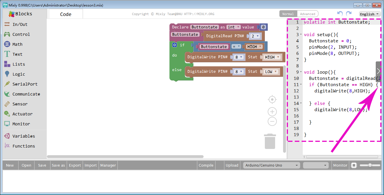
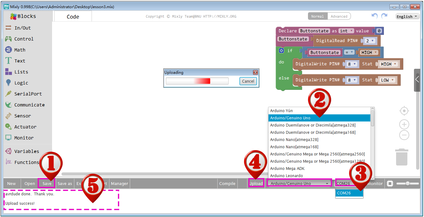
The whole program has complete. You can check equivalent アルドゥイーノC language code on the right bar.
The logic of our program is very simple: When we push Button Switch on D2 slot, アルドゥイーノButtonstate variable will get a HIGH value. When Button is released, Buttonstate will get a LOW value.
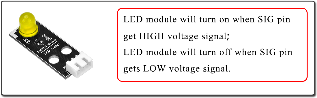
When Buttonstate value is HIGH, then アルドゥイーノwill give D8 a HIGH voltage and turn on LED, if Buttonstate value is LOW, then D8 will output a LOW voltage and turn off LED.

プログラム全体が完成しました。私たちのプログラムのロジックはとても簡単です。D2スロットのボタン・スイッチを押すと、アルドゥイーノの”Buttonstate”変数が”HIGH”の値をとる。”Buttonstate”値がHIGHの場合、アルドゥイーノはD8に”HIGH”の電圧を与えてLEDを点灯させ、”Buttonstate”の値が”LOW”の場合、D8は”LOW”の電圧を出力してLEDを消灯させます

すべてのプログラミングが完了したら、[保存]をクリックします。正しいボードタイプとシリアルポートを選択し、[アップロード]をクリックします最後に、stausは「Uploadsuccess!」に変わります。以下に示すように。

すべての表示されます、「保存」しします。実脚型と台ポートを選択して、アップロードしします。入力、下図のように「アップロード成功!」と表示されます。


*プレイウェイ

ボタンを押すと、LEDモジュールが点灯します。スイッチを離すと、LEDが消灯します。

さて、ボタンを、そして、LEDC1が、そして、LEDが欲しいします。

*応用実験

このプロジェクトにLEDセンサーとボタンを追加するには、このプログラムと同様のロジックを使用します。ボタンスイッチを押すと、1つまたは2つのLEDが点灯します。スイッチを離すと、LEDがオフになります。

オプションが押しボタンと、1つのうち2つのLEDが達成し、押しが離しし、LED押しボタン押しボタンししししししししししししししししししししししししししししししししししししができします。