In order to connect our Things to Internet, we need to select some Internet communication protocol so that different Internet device can talk with each other. Some commonly used IoT protocols are HTTP, MQTT etc.
In this lesson, we will learn how to use HTTP protocol and how to make simple HTTP web server with Osoyoo MEGA-IoT shield and MEGA2560 micro-controller and show a “Hello World!” web page to remote browser . The web page also shows the input voltage of A0 pin that is detected by Arduino analogRead() functions.
OSOYOO Advanced Board for MEGA2560 Board x 1
OSOYOO MEGA-IoT extension board x 1
USB Cable x 1
Male to Male jumper wire x 1
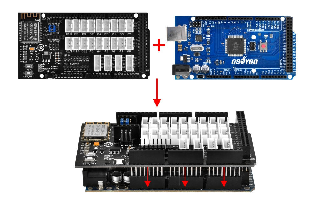
1).please plug OSOYOO MEGA-IoT Extension Board into OSOYOO Advanced Board for MEGA2560 Board:
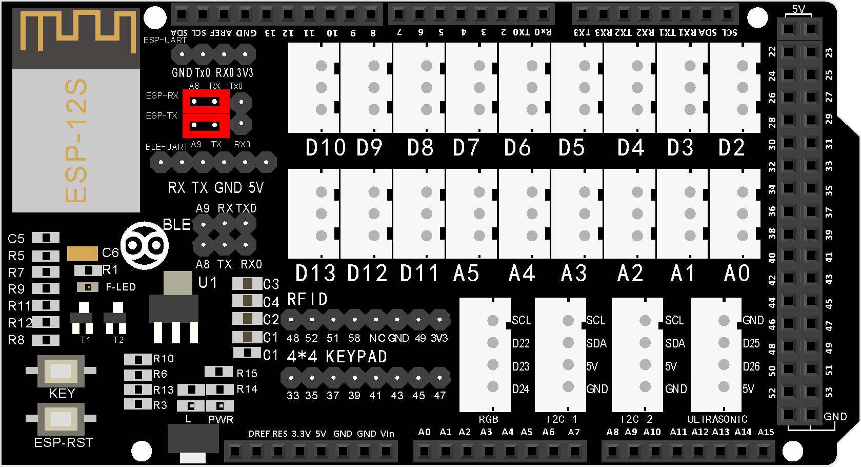
2)Use jumper Cap to connect ESP8266 RX with A8, TX with A9)
SOFTWARE
Software Installation
Notice: Shut off your battery or Unplug your power adapter when upload sketch code to your OSOYOO Advanced Board for Arduino MEGA2560.
Step 2 OSOYOO MEGA-IoT extension TX/RX pin to A9/A8 pin by default. So in your sketch code, we need use Software Serial Port to communicate with ESP8266 (set A9 as TX and A8 as RX in SoftwareSerial object).we need download WiFiEsp-master library from following link firstly: https://osoyoo.com/driver/WiFiEsp-master.zip
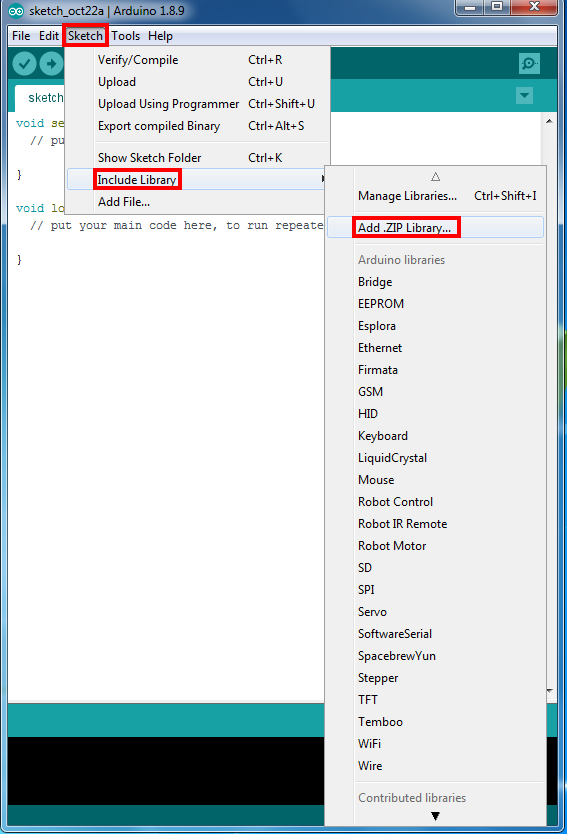
Step3 Open the IDE ->Sketch ->Include Library ->Add ,Zip library to load above zip files into Arduino IDE.
Step 4 After installing above library, please download the main code from following link.unzip the download zip file lesson3.zip, you will see a folder called smarthome-lesson3. https://osoyoo.com/driver/smarthome/smarthome-lesson3.zip
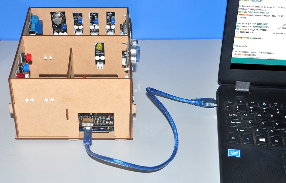
Step 5 After above operations are completed, connect the OSOYOO MEGA2560 Board to the PC with USB cable.
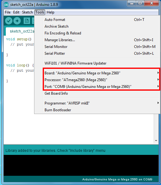
Step 6 Open the IDE and choose corresponding board type and port type for your project.
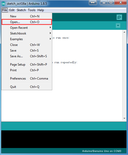
Step 7 IDE: Click file -> click Open -> choose code “smarthome-lesson3”, load the sketch onto your board.
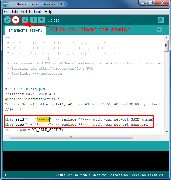
Note: In the sketch, find following lines:
char ssid[] = "******"; // your network SSID (name)
char pass[] = "******"; // your network password
please replace the ****** with your correct wifi SSID and password, otherwise your project can not connect to Internet.
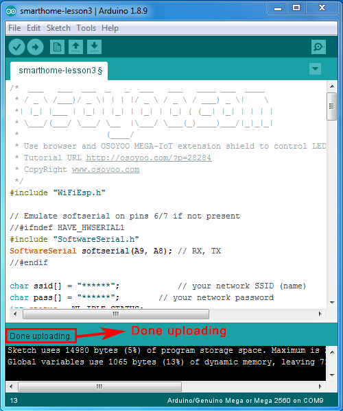
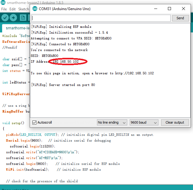
After loading the sketch to IDE , open the serial monitor in the upper-right corner of IDE, you will see following result:
From the serial monitor , you can see the IP address of your MEGA2560 board in the read circle (in above picture, 192.168.50.102).
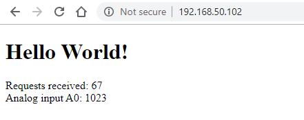
Then use your browser to visit the website http://mega2560-ip-address (in above case, http://192.168.50.102), you will see following result:
Above result also shows the A0 pin input voltage through analogRead(0) function in line 94. analogRead() can read the input 0-5V voltage and return a value between 0 to 1023 standing for the voltage.
If we connect A0 to GND via jumper wire, Analog input A0: shows 0
If we connect A0 to 5V via jumper wire , Analog input A0: shows 1023.
Trouble Shooting
Sometimes when running lesson3 project, ESP8266 might have initialization problem with MEGA2560 A8,A9 pins and this cause WifiESP initializing error showing in Serial monitor as following:
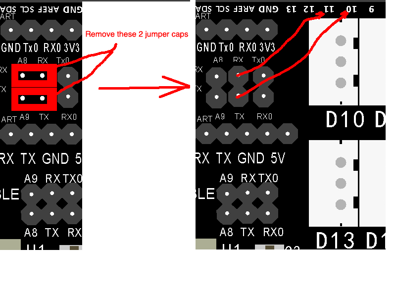
To solve the problem, we need use Stable pin D10,D11 to initialize ESP8266 and then switch back to A8,A9.
To do this, please do as per following steps:
Step 1)remove the jumper caps on A8/ESP_RX and A9/ESP_TX, then use two Female-To-Male jumper wires connect ESP_RX to D11 and ESP_TX to D10,
see following picture:
Above circuit change will use D10, D11 instead of A8, A9 to connect ESP8266 serial port because MEGA2560 A8,A9 is not as stable as D10,D11.
Step 2) Now we need slightly change some code of Lesson 3 sketch file line 15:
Original line 15 is : SoftwareSerial softserial(A9, A8); // RX, TXPlease change above line to: SoftwareSerial softserial(10, 11); // RX, TX
Step 3) Load the sketch to IDE and the Initializing normally will pass through and show
[WiFiEsp] Initilization successful - 1.5.4 SSI
This means your ESP8266 chip has connected to your MEGA2560. Then your OSOYOO Advanced Board for MEGA2560 Board will keep connecting your wifi SSID and Serial Monitor will tell you the IP address.
Once above procedure has been done. You can actually roll back the ESP8266 connection to A8,A9 same as original status, and change line 15 to : SoftwareSerial softserial(A9, A8); // RX, TX
Now load the original Lesson 3 sketch, it will work .
I am getting this error on the serial monitor:
[WiFiEsp] Initializing ESP module
[WiFiEsp] >>> TIMEOUT >>>
[WiFiEsp] >>> TIMEOUT >>>
[WiFiEsp] >>> TIMEOUT >>>
[WiFiEsp] >>> TIMEOUT >>>
[WiFiEsp] >>> TIMEOUT >>>
[WiFiEsp] Cannot initialize ESP module
[WiFiEsp] >>> TIMEOUT >>>
[WiFiEsp] No tag found
WiFi shield not present
Hi Cbales!
I’m running into the same problem but I am sure I have the jumpers right.
What did you end up doing exactly?
Do I need a third jumper on Tx0 and Rx0 or something?
This is the message I am getting – what could I be doing wrong. I checked to make sure the ssid and password are correct and the pins are entered correctly.
[WiFiEsp] Initializing ESP module
[WiFiEsp] >>> TIMEOUT >>>
[WiFiEsp] >>> TIMEOUT >>>
[WiFiEsp] >>> TIMEOUT >>>
[WiFiEsp] >>> TIMEOUT >>>
[WiFiEsp] >>> TIMEOUT >>>
[WiFiEsp] Cannot initialize ESP module
[WiFiEsp] >>> TIMEOUT >>>
[WiFiEsp] No tag found
WiFi shield not present
// Emulate softserial on pins 6/7 if not present
//#ifndef HAVE_HWSERIAL1
#include “SoftwareSerial.h”
SoftwareSerial softserial (10, 11); // RX, TX
//#endif
char ssid[] = “vodafone3418”; // your network SSID (name)
char pass[] = “RJSPSB7TVU78R8”; // your network password
int status = WL_IDLE_STATUS;
int reqCount = 0; // number of requests received
WiFiEspServer server(80);
void setup()
{
// initialize serial for debugging
Serial.begin(9600);
// initialize serial for ESP module
softserial.begin(115200);
softserial.write(“AT+CIOBAUD=9600\r\n”);
softserial.write(“AT+RST\r\n”);
softserial.begin(9600);
// initialize ESP module
WiFi.init(&softserial);
// check for the presence of the shield
if (WiFi.status() == WL_NO_SHIELD) {
Serial.println(“WiFi shield not present”);
// don’t continue
while (true);
}
// attempt to connect to WiFi network
while ( status != WL_CONNECTED) {
Serial.print(“Attempting to connect to WPA SSID: “);
Serial.println(ssid);
// Connect to WPA/WPA2 network
status = WiFi.begin(ssid, pass);
}
Serial.println(“You’re connected to the network”);
printWifiStatus();
// start the web server on port 80
server.begin();
}
void loop()
{
// listen for incoming clients
WiFiEspClient client = server.available();
if (client) {
Serial.println(“New client”);
// an http request ends with a blank line
boolean currentLineIsBlank = true;
while (client.connected()) {
if (client.available()) {
char c = client.read();
Serial.write(c);
// if you’ve gotten to the end of the line (received a newline
// character) and the line is blank, the http request has ended,
// so you can send a reply
if (c == ‘\n’ && currentLineIsBlank) {
Serial.println(“Sending response”);
// send a standard http response header
// use \r\n instead of many println statements to speedup data send
client.print(
“HTTP/1.1 200 OK\r\n”
“Content-Type: text/html\r\n”
“Connection: close\r\n” // the connection will be closed after completion of the response
“Refresh: 20\r\n” // refresh the page automatically every 20 sec
“\r\n”);
client.print(“\r\n”);
client.print(“\r\n”);
client.print(“Hello World!\r\n”);
client.print(“Requests received: “);
client.print(++reqCount);
client.print(“\r\n”);
client.print(“Analog input A0: “);
client.print(analogRead(0));
client.print(“\r\n”);
client.print(“\r\n”);
break;
}
if (c == ‘\n’) {
// you’re starting a new line
currentLineIsBlank = true;
}
else if (c != ‘\r’) {
// you’ve gotten a character on the current line
currentLineIsBlank = false;
}
}
}
// give the web browser time to receive the data
delay(10);
// close the connection:
client.stop();
Serial.println(“Client disconnected”);
}
}
void printWifiStatus()
{
// print the SSID of the network you’re attached to
Serial.print(“SSID: “);
Serial.println(WiFi.SSID());
// print your WiFi shield’s IP address
IPAddress ip = WiFi.localIP();
Serial.print(“IP Address: “);
Serial.println(ip);
// print where to go in the browser
Serial.println();
Serial.print(“To see this page in action, open a browser to http://“);
Serial.println(ip);
Serial.println();
}
y ya esta . Y ademas quitar los jumpers y conectar lo de un cable macho hembra a los dos pines que te dice .
The wifi module works when I do the troubleshooting steps for connecting to 10, 11. However, when I try to roll back to the A8, A9 it is not working.
can anyone help by showing a picture of how the cables should be connected to A8, A9 — do i use the pnp jumpers or do i use the regualr jumper cables. Please help.
// Emulate softserial on pins 6/7 if not present
//#ifndef HAVE_HWSERIAL1
#include “SoftwareSerial.h”
SoftwareSerial softserial(10, 11); // RX, TX
//SoftwareSerial softserial(A9, A8); // RX, TX
//#endif
char ssid[] = “TEST”; // your network SSID (name)
char pass[] = “0001234”; // your network password
int status = WL_IDLE_STATUS;
int reqCount = 0; // number of requests received
WiFiEspServer server(80);
void setup()
{
// initialize serial for debugging
Serial.begin(9600);
// initialize serial for ESP module
softserial.begin(115200);
softserial.write(“AT+CIOBAUD=9600\r\n”);
softserial.write(“AT+RST\r\n”);
softserial.begin(9600);
// initialize ESP module
WiFi.init(&softserial);
// check for the presence of the shield
if (WiFi.status() == WL_NO_SHIELD) {
Serial.println(“WiFi shield not present”);
// don’t continue
while (true);
}
// attempt to connect to WiFi network
while ( status != WL_CONNECTED) {
Serial.print(“Attempting to connect to WPA SSID: “);
Serial.println(ssid);
// Connect to WPA/WPA2 network
status = WiFi.begin(ssid, pass);
}
Serial.println(“You’re connected to the network”);
printWifiStatus();
// start the web server on port 80
server.begin();
}
void loop()
{
// listen for incoming clients
WiFiEspClient client = server.available();
if (client) {
Serial.println(“New client”);
// an http request ends with a blank line
boolean currentLineIsBlank = true;
while (client.connected()) {
if (client.available()) {
char c = client.read();
Serial.write(c);
// if you’ve gotten to the end of the line (received a newline
// character) and the line is blank, the http request has ended,
// so you can send a reply
if (c == ‘\n’ && currentLineIsBlank) {
Serial.println(“Sending response”);
// send a standard http response header
// use \r\n instead of many println statements to speedup data send
client.print(
“HTTP/1.1 200 OK\r\n”
“Content-Type: text/html\r\n”
“Connection: close\r\n” // the connection will be closed after completion of the response
“Refresh: 20\r\n” // refresh the page automatically every 20 sec
“\r\n”);
client.print(“\r\n”);
client.print(“\r\n”);
client.print(“Hello World!\r\n”);
client.print(“Requests received: “);
client.print(++reqCount);
client.print(“\r\n”);
client.print(“Analog input A0: “);
client.print(analogRead(0));
client.print(“\r\n”);
client.print(“\r\n”);
break;
}
if (c == ‘\n’) {
// you’re starting a new line
currentLineIsBlank = true;
}
else if (c != ‘\r’) {
// you’ve gotten a character on the current line
currentLineIsBlank = false;
}
}
}
// give the web browser time to receive the data
delay(10);
// close the connection:
client.stop();
Serial.println(“Client disconnected”);
}
}
void printWifiStatus()
{
// print the SSID of the network you’re attached to
Serial.print(“SSID: “);
Serial.println(WiFi.SSID());
// print your WiFi shield’s IP address
IPAddress ip = WiFi.localIP();
Serial.print(“IP Address: “);
Serial.println(ip);
// print where to go in the browser
Serial.println();
Serial.print(“To see this page in action, open a browser to http://“);
Serial.println(ip);
Serial.println();
}
but the serial monitor shows me the following message:
[WiFiEsp] >>> TIMEOUT >>>
[WiFiEsp] >>> TIMEOUT >>>
[WiFiEsp] >>> TIMEOUT >>>
[WiFiEsp] >>> TIMEOUT >>>
[WiFiEsp] Cannot initialize ESP module
[WiFiEsp] >>> TIMEOUT >>>
[WiFiEsp] No tag found
WiFi shield not present


I am getting this error on the serial monitor:
[WiFiEsp] Initializing ESP module
[WiFiEsp] >>> TIMEOUT >>>
[WiFiEsp] >>> TIMEOUT >>>
[WiFiEsp] >>> TIMEOUT >>>
[WiFiEsp] >>> TIMEOUT >>>
[WiFiEsp] >>> TIMEOUT >>>
[WiFiEsp] Cannot initialize ESP module
[WiFiEsp] >>> TIMEOUT >>>
[WiFiEsp] No tag found
WiFi shield not present
Does this mean that my ESP shield is bad?
Nevermind. I solved the problem. The diagram showing the jumper cap connection is not very descriptive.
Hi Cbales!
I’m running into the same problem but I am sure I have the jumpers right.
What did you end up doing exactly?
Do I need a third jumper on Tx0 and Rx0 or something?
Check if your hotspot name and password are correct
Nevermind Cbales:
I had some bent pins on the board.
This is the message I am getting – what could I be doing wrong. I checked to make sure the ssid and password are correct and the pins are entered correctly.
[WiFiEsp] Initializing ESP module
[WiFiEsp] >>> TIMEOUT >>>
[WiFiEsp] >>> TIMEOUT >>>
[WiFiEsp] >>> TIMEOUT >>>
[WiFiEsp] >>> TIMEOUT >>>
[WiFiEsp] >>> TIMEOUT >>>
[WiFiEsp] Cannot initialize ESP module
[WiFiEsp] >>> TIMEOUT >>>
[WiFiEsp] No tag found
WiFi shield not present
tienes que descargarte la carpeta que te dan de wifiESP-master.zip y adjuntarla a la librería . Y después , cambiar el código a :
/* ___ ___ ___ _ _ ___ ___ ____ ___ ____
* / _ \ /___)/ _ \| | | |/ _ \ / _ \ / ___) _ \| \
*| |_| |___ | |_| | |_| | |_| | |_| ( (__| |_| | | | |
* \___/(___/ \___/ \__ |\___/ \___(_)____)___/|_|_|_|
* (____/
* Use browser and OSOYOO MEGA-IoT extension shield to control LED from remote browser
* Tutorial URL http://osoyoo.com/?p=28284
* CopyRight http://www.osoyoo.com
*/
#include “WiFiEsp.h”
// Emulate softserial on pins 6/7 if not present
//#ifndef HAVE_HWSERIAL1
#include “SoftwareSerial.h”
SoftwareSerial softserial (10, 11); // RX, TX
//#endif
char ssid[] = “vodafone3418”; // your network SSID (name)
char pass[] = “RJSPSB7TVU78R8”; // your network password
int status = WL_IDLE_STATUS;
int reqCount = 0; // number of requests received
WiFiEspServer server(80);
void setup()
{
// initialize serial for debugging
Serial.begin(9600);
// initialize serial for ESP module
softserial.begin(115200);
softserial.write(“AT+CIOBAUD=9600\r\n”);
softserial.write(“AT+RST\r\n”);
softserial.begin(9600);
// initialize ESP module
WiFi.init(&softserial);
// check for the presence of the shield
if (WiFi.status() == WL_NO_SHIELD) {
Serial.println(“WiFi shield not present”);
// don’t continue
while (true);
}
// attempt to connect to WiFi network
while ( status != WL_CONNECTED) {
Serial.print(“Attempting to connect to WPA SSID: “);
Serial.println(ssid);
// Connect to WPA/WPA2 network
status = WiFi.begin(ssid, pass);
}
Serial.println(“You’re connected to the network”);
printWifiStatus();
// start the web server on port 80
server.begin();
}
void loop()
{
// listen for incoming clients
WiFiEspClient client = server.available();
if (client) {
Serial.println(“New client”);
// an http request ends with a blank line
boolean currentLineIsBlank = true;
while (client.connected()) {
if (client.available()) {
char c = client.read();
Serial.write(c);
// if you’ve gotten to the end of the line (received a newline
// character) and the line is blank, the http request has ended,
// so you can send a reply
if (c == ‘\n’ && currentLineIsBlank) {
Serial.println(“Sending response”);
// send a standard http response header
// use \r\n instead of many println statements to speedup data send
client.print(
“HTTP/1.1 200 OK\r\n”
“Content-Type: text/html\r\n”
“Connection: close\r\n” // the connection will be closed after completion of the response
“Refresh: 20\r\n” // refresh the page automatically every 20 sec
“\r\n”);
client.print(“\r\n”);
client.print(“\r\n”);
client.print(“Hello World!\r\n”);
client.print(“Requests received: “);
client.print(++reqCount);
client.print(“\r\n”);
client.print(“Analog input A0: “);
client.print(analogRead(0));
client.print(“\r\n”);
client.print(“\r\n”);
break;
}
if (c == ‘\n’) {
// you’re starting a new line
currentLineIsBlank = true;
}
else if (c != ‘\r’) {
// you’ve gotten a character on the current line
currentLineIsBlank = false;
}
}
}
// give the web browser time to receive the data
delay(10);
// close the connection:
client.stop();
Serial.println(“Client disconnected”);
}
}
void printWifiStatus()
{
// print the SSID of the network you’re attached to
Serial.print(“SSID: “);
Serial.println(WiFi.SSID());
// print your WiFi shield’s IP address
IPAddress ip = WiFi.localIP();
Serial.print(“IP Address: “);
Serial.println(ip);
// print where to go in the browser
Serial.println();
Serial.print(“To see this page in action, open a browser to http://“);
Serial.println(ip);
Serial.println();
}
y ya esta . Y ademas quitar los jumpers y conectar lo de un cable macho hembra a los dos pines que te dice .
I’m running into the same problem. The pins are OK.
What shall I do ?
Hi gents
I get the same problem and jumpers seem to be ok
How did you solve yours?
The wifi module works when I do the troubleshooting steps for connecting to 10, 11. However, when I try to roll back to the A8, A9 it is not working.
can anyone help by showing a picture of how the cables should be connected to A8, A9 — do i use the pnp jumpers or do i use the regualr jumper cables. Please help.
I’ll reply you by email
Hi David,
I havent received the reply yet.
Thanks
have you sent it yet?
The mailbox prompts that the mail was delivered successfully
can someone help me!
Hi everyone i´m trying to start wifi ESP with the following code
/* ___ ___ ___ _ _ ___ ___ ____ ___ ____
* / _ \ /___)/ _ \| | | |/ _ \ / _ \ / ___) _ \| \
*| |_| |___ | |_| | |_| | |_| | |_| ( (__| |_| | | | |
* \___/(___/ \___/ \__ |\___/ \___(_)____)___/|_|_|_|
* (____/
* Use browser and OSOYOO MEGA-IoT extension shield to control LED from remote browser
* Tutorial URL http://osoyoo.com/?p=28284
* CopyRight http://www.osoyoo.com
*/
#include “WiFiEsp.h”
// Emulate softserial on pins 6/7 if not present
//#ifndef HAVE_HWSERIAL1
#include “SoftwareSerial.h”
SoftwareSerial softserial(10, 11); // RX, TX
//SoftwareSerial softserial(A9, A8); // RX, TX
//#endif
char ssid[] = “TEST”; // your network SSID (name)
char pass[] = “0001234”; // your network password
int status = WL_IDLE_STATUS;
int reqCount = 0; // number of requests received
WiFiEspServer server(80);
void setup()
{
// initialize serial for debugging
Serial.begin(9600);
// initialize serial for ESP module
softserial.begin(115200);
softserial.write(“AT+CIOBAUD=9600\r\n”);
softserial.write(“AT+RST\r\n”);
softserial.begin(9600);
// initialize ESP module
WiFi.init(&softserial);
// check for the presence of the shield
if (WiFi.status() == WL_NO_SHIELD) {
Serial.println(“WiFi shield not present”);
// don’t continue
while (true);
}
// attempt to connect to WiFi network
while ( status != WL_CONNECTED) {
Serial.print(“Attempting to connect to WPA SSID: “);
Serial.println(ssid);
// Connect to WPA/WPA2 network
status = WiFi.begin(ssid, pass);
}
Serial.println(“You’re connected to the network”);
printWifiStatus();
// start the web server on port 80
server.begin();
}
void loop()
{
// listen for incoming clients
WiFiEspClient client = server.available();
if (client) {
Serial.println(“New client”);
// an http request ends with a blank line
boolean currentLineIsBlank = true;
while (client.connected()) {
if (client.available()) {
char c = client.read();
Serial.write(c);
// if you’ve gotten to the end of the line (received a newline
// character) and the line is blank, the http request has ended,
// so you can send a reply
if (c == ‘\n’ && currentLineIsBlank) {
Serial.println(“Sending response”);
// send a standard http response header
// use \r\n instead of many println statements to speedup data send
client.print(
“HTTP/1.1 200 OK\r\n”
“Content-Type: text/html\r\n”
“Connection: close\r\n” // the connection will be closed after completion of the response
“Refresh: 20\r\n” // refresh the page automatically every 20 sec
“\r\n”);
client.print(“\r\n”);
client.print(“\r\n”);
client.print(“Hello World!\r\n”);
client.print(“Requests received: “);
client.print(++reqCount);
client.print(“\r\n”);
client.print(“Analog input A0: “);
client.print(analogRead(0));
client.print(“\r\n”);
client.print(“\r\n”);
break;
}
if (c == ‘\n’) {
// you’re starting a new line
currentLineIsBlank = true;
}
else if (c != ‘\r’) {
// you’ve gotten a character on the current line
currentLineIsBlank = false;
}
}
}
// give the web browser time to receive the data
delay(10);
// close the connection:
client.stop();
Serial.println(“Client disconnected”);
}
}
void printWifiStatus()
{
// print the SSID of the network you’re attached to
Serial.print(“SSID: “);
Serial.println(WiFi.SSID());
// print your WiFi shield’s IP address
IPAddress ip = WiFi.localIP();
Serial.print(“IP Address: “);
Serial.println(ip);
// print where to go in the browser
Serial.println();
Serial.print(“To see this page in action, open a browser to http://“);
Serial.println(ip);
Serial.println();
}
but the serial monitor shows me the following message:
[WiFiEsp] >>> TIMEOUT >>>
[WiFiEsp] >>> TIMEOUT >>>
[WiFiEsp] >>> TIMEOUT >>>
[WiFiEsp] >>> TIMEOUT >>>
[WiFiEsp] Cannot initialize ESP module
[WiFiEsp] >>> TIMEOUT >>>
[WiFiEsp] No tag found
WiFi shield not present