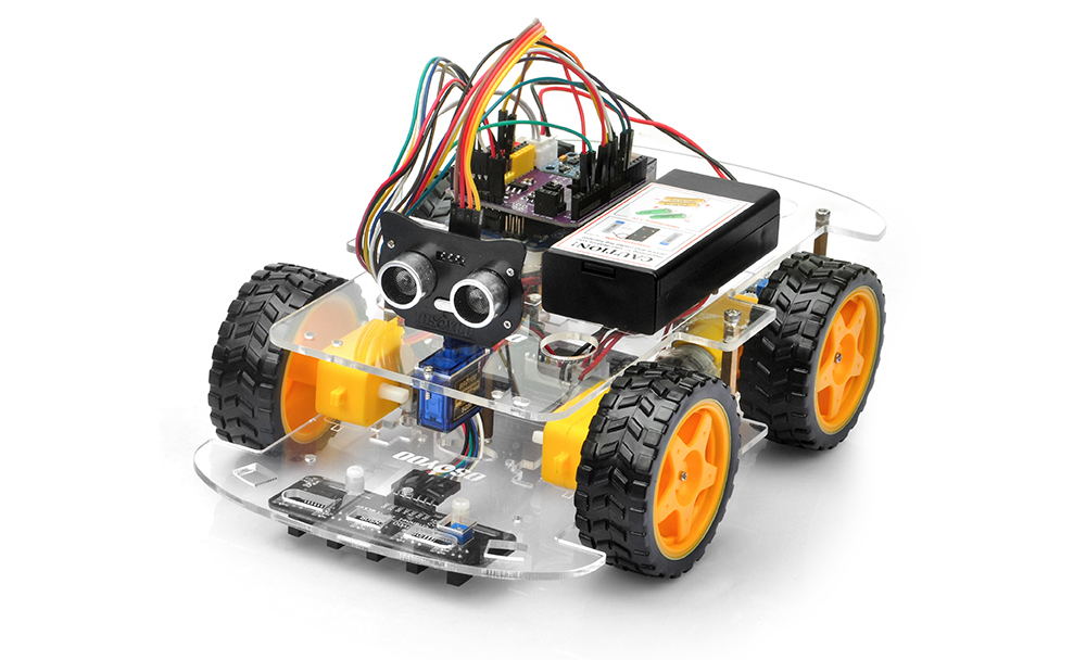
In this lesson, you will transform your OSOYOO V3 Robot Car into a WiFi-connected mobile robot using the OSOLINK WiFi/BLE I/O Shield, which integrates an ESP32-C3 wireless communication module.
Instead of relying on wired connections or short-range infrared control, the robot communicates wirelessly with a smartphone through WiFi. This enables responsive remote control while introducing the fundamentals of Internet of Things (IoT) and networked robotics.
The OSOLINK Shield serves as a dedicated wireless communication interface between the Arduino controller and the mobile application. By offloading WiFi networking to the onboard ESP32-C3 module, the Arduino can focus on real-time motor control and sensor processing, resulting in a more reliable and responsive robotic system.
During this lesson, you will learn how to configure the robot in both Access Point (AP) and Station (STA) modes, establish wireless communication with a mobile device, and understand how modern robots integrate embedded controllers with wireless networking technologies.
After completing this lesson, you will be able to:
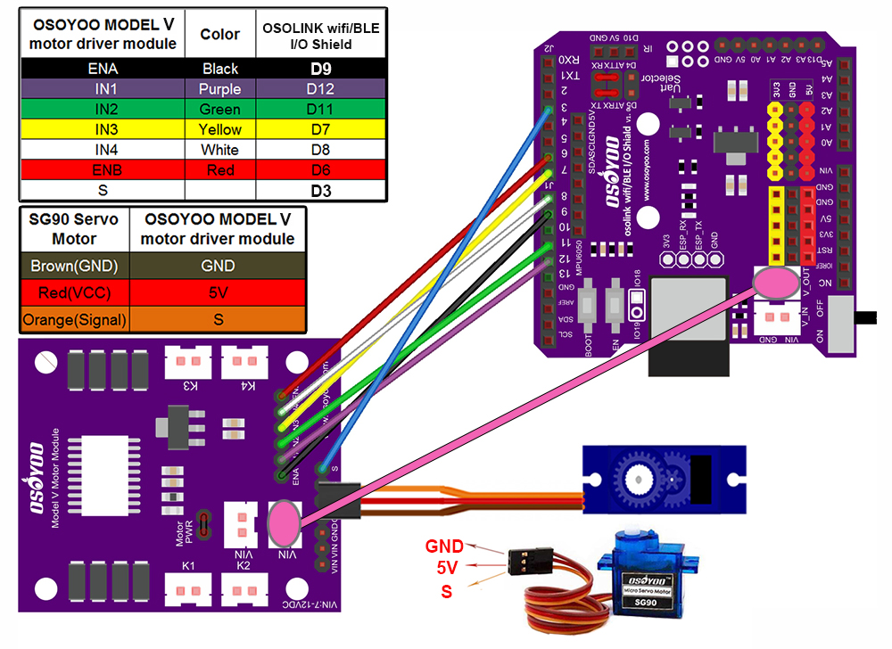
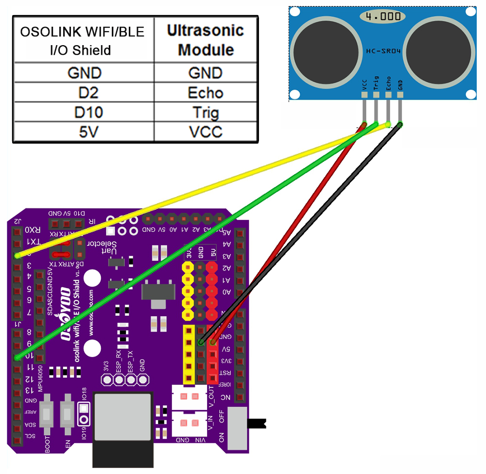
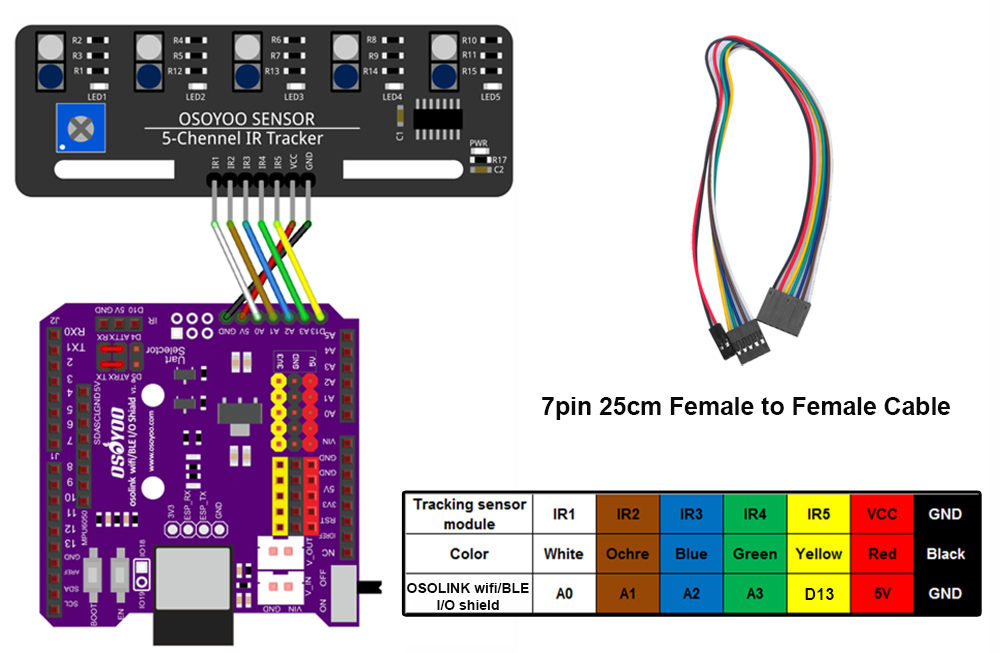
Step 1: Install the smart car as per lesson 1, lesson 4 and lesson 5. If you have completed these lessons, You can skip all steps as following. If you complete lesson 2 and lesson 3, please remove wires on D2 and D3.
Step 2: Check the wiring diagram provided in the lesson package.
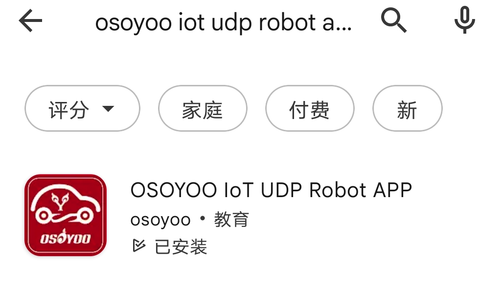
search “Osoyoo IoT UDP Robot APP” in
Google Play or Apple Store(If you can not find this APP in Google Play,
you can directly download the APP from following link: https://osoyoo.com/driver/udp-app.apk)
1) Download OSOYOO Wi-Fi UDP Robot Car control APP
In Google Play or Apple APP Store, please search keywords “OSOYOO IoT UDP Robot APP”, you will find a red icon APP as following (Note: If you can not find this APP in Google Play, you can directly download the APP from following link: https://osoyoo.com/driver/udp-app.apk ):
2) Osoyoo V3 Robot Car can work in two WIFI modes: STA mode and AP mode. The sketches for these two modes are different. Let’s explain these two modes one by one
5 STA mode
In STA mode, OSOYOO V3 Robot Car kit will be a client device of your LAN router. You need save the SSID name and password of your LAN router in sketch.
Once the sketch is running, your router DHCP service will assign an IP address to your robot car and your APP will use this IP address to access your car. 1. Upload code for STA mode
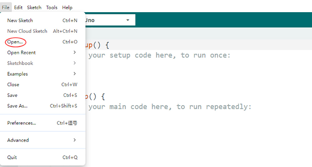
Step 1. Please download STA mode sketch code from here. Extract the contents and you will get a v3car-lesson6A.ino in the folder v3car-lesson6A. Open the v3car-lesson6A.ino sketch in the Arduino IDE.
Step 2. Install Libraries:
Firstly, download Libraries zip files from following links:
ServoTimer2 library: https://osoyoo.com/driver/ServoTimer2-master.zip
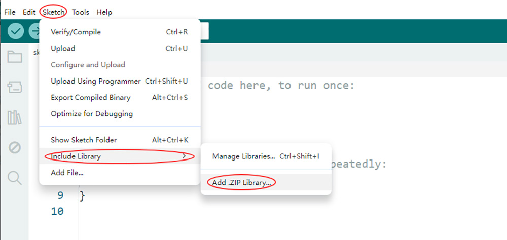
Second, do NOT unzip them, open Arduino IDE ->Sketch ->Include Library ->Add Zip Library. Then upload above zip file to Arduino IDE.
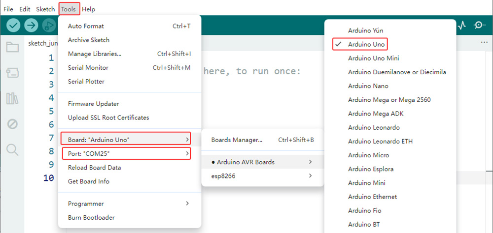
Step 3. Connect the OSOYOO Basic Board (compatible with Arduino UNO) to your computer via a USB cable(Crucially, ensure the robot car’s power switch is OFF and the battery is disconnected before connect the board to your PC). Launch the Arduino IDE. Navigate to Tools > Board and select Arduino Uno. Then, go to Tools > Port and select the appropriate serial port. If unsure, check your operating system’s device manager for the assigned port.
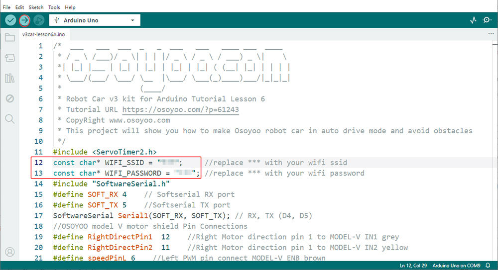
step 4. You need change the code Line 12 and Line 13 : const char* WIFI_SSID = “***”; //replace *** with your wifi ssid const char* WIFI_PASSWORD = “***”; //replace *** with your wifi password
Step 5. Upload the sketch to your board.
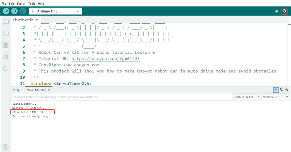
Step 6. click the Serial monitor in upper right corner of IDE, you will see following result:
In above picture, the 192.168.0.31 is your robot car IP address. Please set this IP address to APP so that APP can exchange data with the robot car.
2. Osoyoo IoT UDP Robot APP setting
In STA mode, you need connect cell phone to the same LAN ssid of your robot car and set IP address same as the Robot IP showed in Serial Monitor.
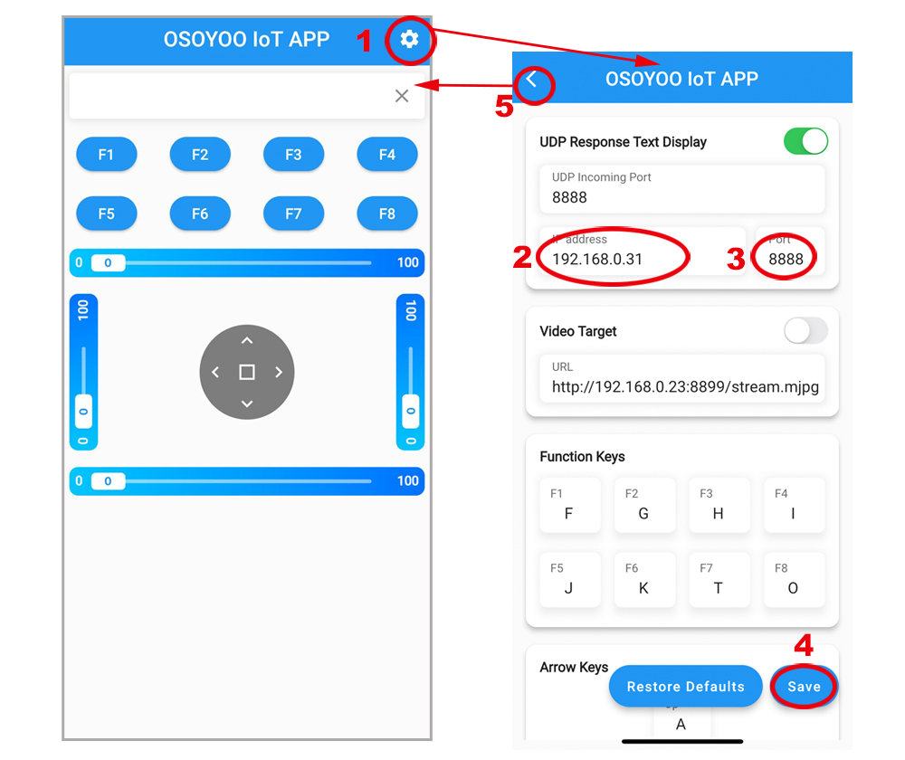
Connect your phone with the same router Wi-Fi SSID as the Arduino board. Open the APP, click “settings icon(1)” to enter setting UI, enter your robot car IP address and Port to 8888, click Save, then click back icon(5) to back control UI.
Example: If your Robot Car IP is 192.168.0.31, you can set the APP as following pictures:
Now your Robot car is connected to your LAN, you can use Mobile phone under same LAN to control the robot car. If your APP is in WAN, you need to go to your Router Control Panel and use Router IP to control the car. This feature makes our robot car A REAL INTERNET OF THING device 3. Final Testing:
Turn on the car. Now click Setting to set up robot IP address. In STA mode, you need connect cell phone to the same LAN ssid of your robot car .
you can click the ◄ ► ▲ ▼ direction keys to make the car move. Use || pause key to stop the car movement.
If you click F8 key, the car will do obstacle avoidance auto driving similar to Lesson 5. Before using obstacle avoidance function, please Alignment Ultrasonic Sensor
If you click F7 key, the car will do link tracking auto driving similar to lesson 4, Before using obstacle avoidance function, please Calibration tracking sensor
6 AP mode
Sometimes we do not have a LAN or WIFI Router. In order to control the car, we need to use AP mode.
When working in AP mode, our robot car itself will become a WIFI Hot Spot. Our cell phone can connect to Robot Car as its wifi client. The IP address of Robot is fixed as 192.168.4.1 and It is not connected to WAN. 1. Upload code for AP mode
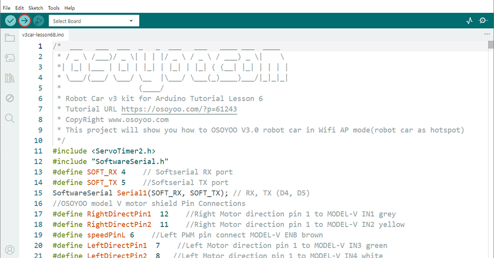
Step 1: Please download AP mode sketch code from here. Extract the contents and you will get a v3car-lesson6B.ino in the folder v3car-lesson6B. Open the v3car-lesson6B.ino sketch in the Arduino IDE.
Step 2: Install Libraries:
Firstly, download Libraries zip files from following links:
ServoTimer2 library: https://osoyoo.com/driver/ServoTimer2-master.zip
Second, do NOT unzip them, open Arduino IDE ->Sketch ->Include Library ->Add Zip Library. Then upload above zip files to Arduino One by One.
Step 3. Connect the OSOYOO Basic Board (compatible with Arduino UNO) to your computer via a USB cable(Crucially, ensure the robot car’s power switch is OFF and the battery is disconnected before connect the board to your PC). Launch the Arduino IDE. Navigate to Tools > Board and select Arduino Uno. Then, go to Tools > Port and select the appropriate serial port. If unsure, check your operating system’s device manager for the assigned port.
Step 4. Click the “Upload” button (right arrow icon) to compile and transfer the sketch to OSOYOO Basic Board.
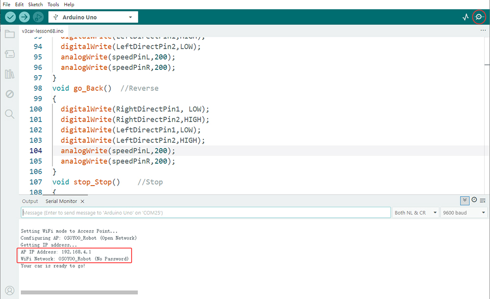
Step 5: Open Serial monitor, and you will see a similar result as STA mode. A new WIFI SSID “OSOYOO_Robot” with IP address 192.168.4.1 will show up in the window. This means your Robot car has a WIFI Hot Spot name “OSOYOO_Robot” , its IP address is 192.168.4.1. 2. Osoyoo IoT UDP Robot APP setting
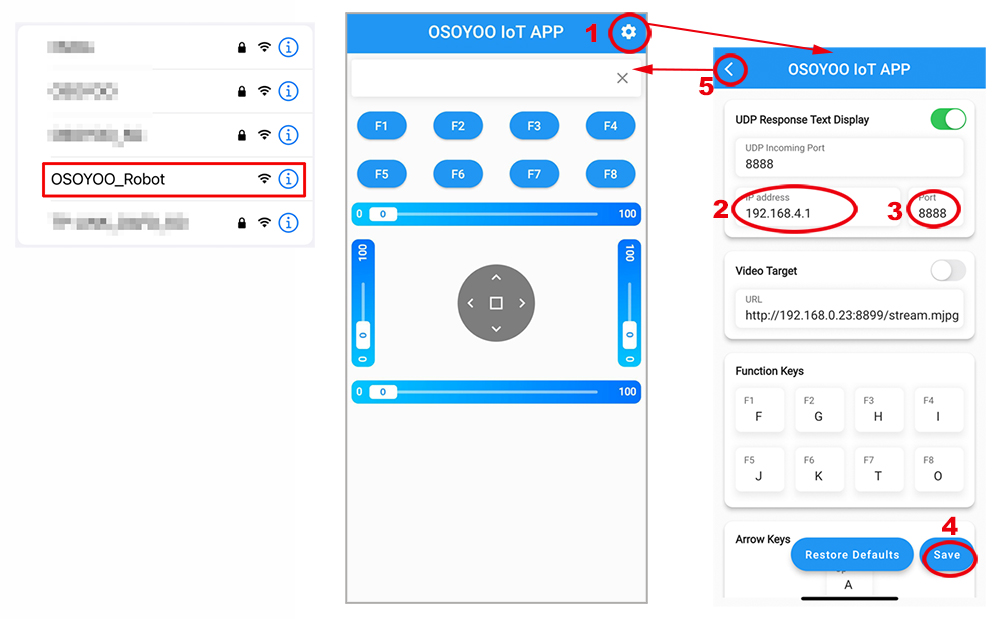
Connect your cell phone to “osoyoo_robot” wifi hot_spot, and set IP address as “192.168.4.1” and port to 8888 to your APP Setting section
Now your Robot car become a WIFI Hot Spot, you can use Mobile phone control the robot car. 3. Final Testing
Turn on the car. Now click Setting to set up robot IP address. In AP mode , you need contact your cell phone to “osoyoo_robot” wifi hot_spot and set IP address as 192.168.4.1
you can click the ◄ ► ▲ ▼ direction keys to make the car move. Use || pause key to stop the car movement.
If you click F8 key, the car will do obstacle avoidance auto driving similar to Lesson 5. Before using obstacle avoidance function, please Alignment Ultrasonic Sensor
If you click F7 key, the car will do link tracking auto driving similar to lesson 4, Before using obstacle avoidance function, please Calibration tracking sensor
7 Troubleshooting
1. Cannot Connect to WiFi
Check:
SSID configuration
WiFi password
Router settings
ESP8266 wiring
2. Application Cannot Control Robot
Verify:
Robot IP address
Port number (8888)
Phone and robot are on the same network
3. Serial Monitor Displays
[WiFiEsp] >>> TIMEOUT >>>
This usually indicates an ESP32 communication problem.