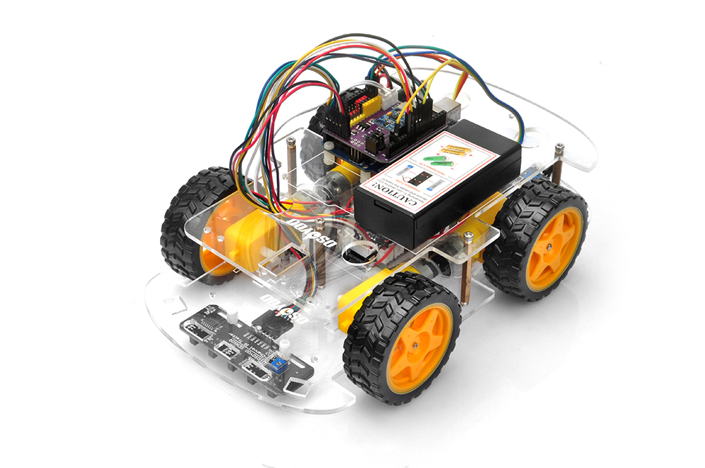
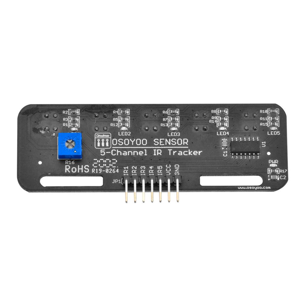
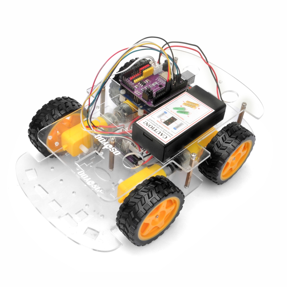
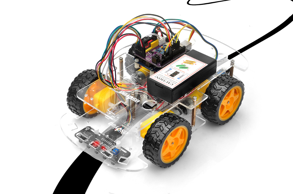
In this lesson, you will transform your OSOYOO V3 Robot Car into an autonomous line-following robot.
Using a 5-channel infrared line tracking sensor array, the robot can detect the position of a black line on a light-colored surface and continuously adjust its direction to stay on the track.
Line following is one of the most fundamental technologies used in mobile robotics and automated guided vehicles (AGVs). It provides an excellent introduction to sensor-based navigation and real-time decision-making.
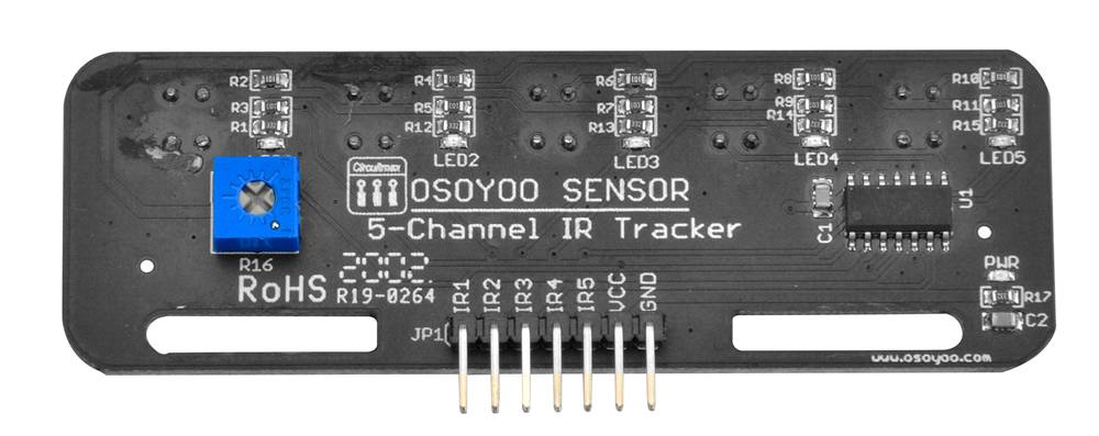
Each tracking sensor contains two components: an infrared LED (emitter) and an infrared phototransistor (receiver).
The infrared LED continuously emits invisible infrared light toward the ground.
The amount of reflected infrared light depends on the surface color: White Surface and Black Surface. White surfaces reflect most of the infrared light. As a result:
Strong reflected signal
Sensor detects HIGH reflection
Receiver output changes state
Black surfaces absorb most of the infrared light. As a result:
Weak reflected signal
Sensor detects LOW reflection
Receiver output changes state
This difference allows the robot to distinguish between the black track and the surrounding white background.
4Hardware Installation
Step 1: Start with the robot assembled in Lesson 1. If you have already completed Lesson 2 and Lesson 3, just keep it as is.
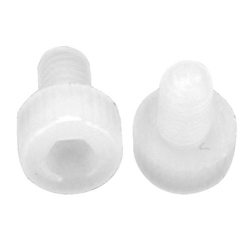
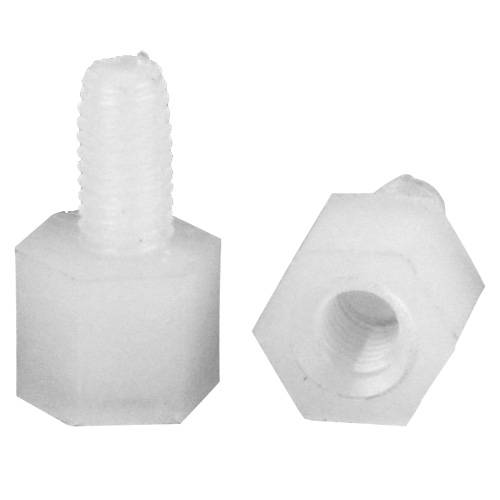
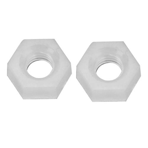
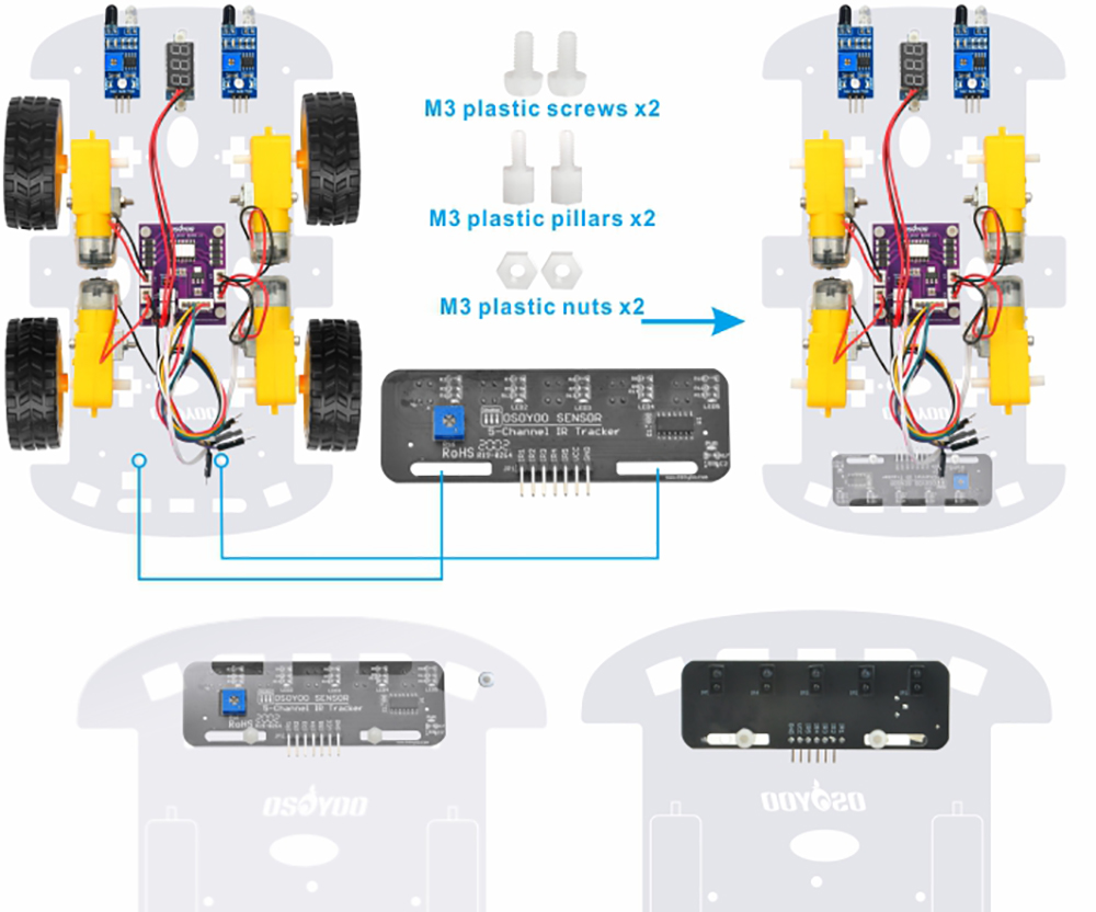
Step 2: Remove the M3 hex screw on the upper chassis. Mount the 5-channel tracking module at the front of the lower chassis using M3 plastic screws, pillars, and nuts.
Important Notes
Sensor heads must face downward.
Sensors should be positioned under the lower chassis.
The blue potentiometer on the sensor should be positioned at the opening square at the front of the lower chassis.
Maintain a consistent distance between the sensors and the ground.
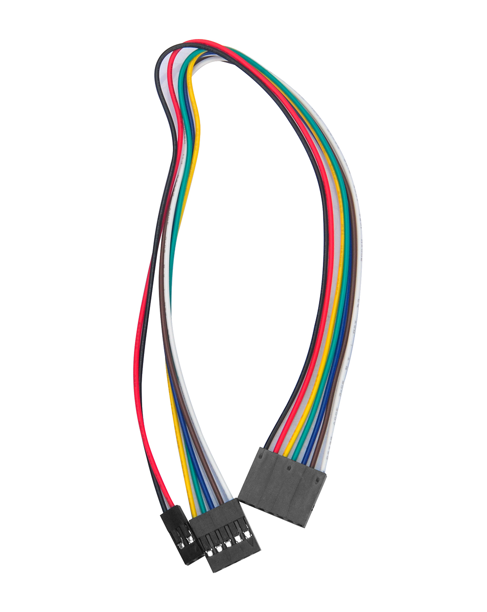
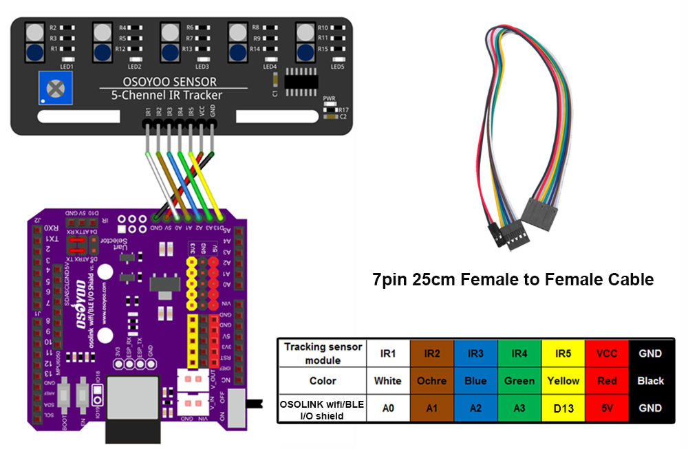
Step 3: Connect the GND–VCC pin of the tracking sensor module to the GND–5V of the OSOLINK WIFI/BLE I/O shield; connect IR1, IR2, IR3, IR4, IR5 pins to A0, A1, A2, A3, D13 with a 7pin 25cm female-to-female cable as shown in the photo below (Remember: DO NOT remove any existing wires installed in Lesson 1):
Step 4: Reinstall the upper chassis and tighten all mounting screws.
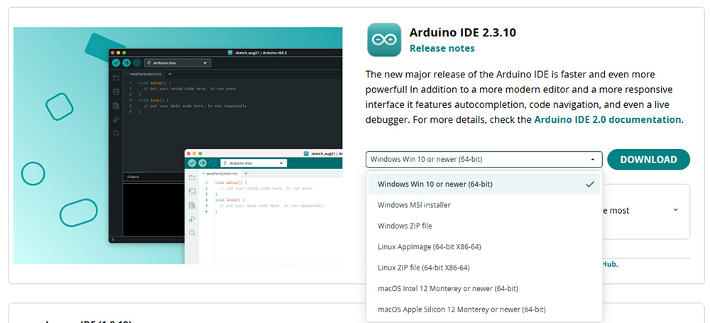
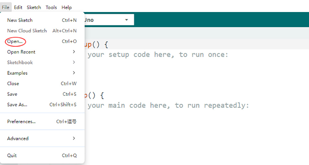
2. Code Acquisition: Download the provided sample code for Lesson 4 from here. Extract the contents and you will get a v3car-lesson4.ino in the folder v3car-lesson4. Open the v3car-lesson4.ino sketch in the Arduino IDE.
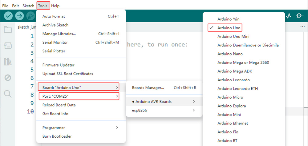
3. Board and Port Selection: Connect the OSOYOO Basic Board (compatible with Arduino UNO) to your computer via a USB cable (Crucially, ensure the robot car’s power switch is OFF and the battery is disconnected before connecting the board to your PC). Launch the Arduino IDE. Navigate to Tools > Board and select Arduino Uno. Then go to Tools > Port and select the appropriate serial port. If unsure, check your operating system’s device manager for the assigned port.
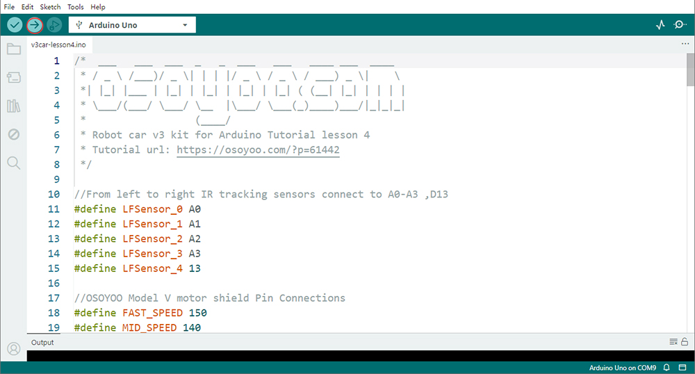
4. Code Upload: Click the “Upload” button (right arrow icon) to compile and transfer the sketch to the OSOYOO Basic Board.
6Sensor Calibration
Proper calibration is essential for reliable line tracking.
Calibration Procedure
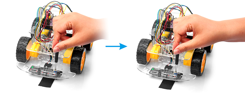
Power on the robot, and hold your robot car.
Place the sensor over a black line on a white surface.
Adjust the onboard potentiometer using a small screwdriver.
Observe the indicator LED.
Surface
Indicator LED
White background
OFF
Black track
ON
7Test the Car
Create a black line on a white surface, and place the center sensor above the black line. Turn on the robot and observe the tracking behavior.
Recommended Track Specifications
Track width: 20–30 mm
High contrast between line and background
Smooth surface
Expected Behavior
Robot follows the line automatically.
Robot corrects its direction when drifting left or right.
Robot maintains alignment with the track.
8Troubleshooting
1. Robot Cannot Detect the Line
Check:
Sensor wiring
Sensor height
Sensor calibration
Battery voltage
2. Robot Frequently Loses the Line
Possible causes:
Track is too narrow
Curves are too sharp
Sensor sensitivity is too low
3. Robot Turns Excessively
Possible causes:
Uneven sensor calibration
Sensor module mounted at an angle
Surface reflections affecting detection
4. Ambient Light Interference
Strong sunlight may affect infrared sensors.
For best performance:
Test indoors
Avoid direct sunlight
Avoid highly reflective surfaces
Infrared tracking sensors are most reliable under controlled lighting conditions.
The updated code improves on the previous algorithm by individually programming the power and direction for the left and right motors, allowing for precise control over turning intensity. It also introduces a sensors variable that quantifies how far the rover has drifted from the black tracking line—negative values indicate the line is to the right, while positive values mean it’s to the left. The turning force is then scaled based on this offset, essentially acting as a simplified PID mechanism.