概述
上一课中,我们学会了如何用Raspberry Pi驱动IIC 1602 LCD,在本课中,我们将结合电位器,设计一个电压表,将电压值再1602 LCD上显示出来。
所用器件
1 * Raspberry Pi
1 * Breadboard
1 * Potentiometer(10kΩ)
1 * IIC 1602 LCD
Several jumper wires
工作原理
电位器又叫可变电阻器,是一种具有三个端子,其中有两个固定接点与一个滑动接点,可经由滑动而改变滑动端与两个固定端间电阻值的电子零件,如图所示
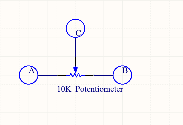
其中,A、B是固定接点,C为滑动接点。
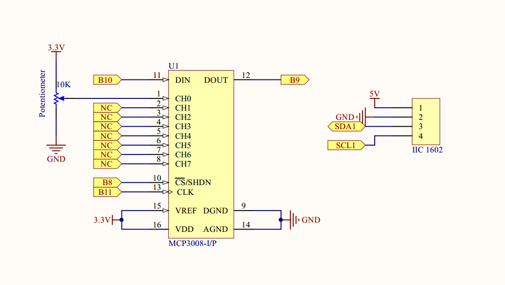
在本课中我们MCP3008读取点位器电压值,经过ADC转换后,Pi读取转换后的AD值,并将其计算成对应电压值,显示在1602上,原理图如下
实物连线
没画(o(╯□╰)o)
软件
打开SPI和IIC接口,具体操作前看lesson10和lesson13
for C language user
1) 在/home/pi下新建一个.c源文件(文件名随意)
cd ~
sudo nano voltmeter.c
2) 往新建的文件中写入一下代码
#include <stdint.h>
#include <string.h>
#include <errno.h>
#include <wiringPi.h>
#include <stdio.h>
#include <stdlib.h>
#include <wiringPiSPI.h>
#include <wiringPiI2C.h>

#define LCDADDR             0x3F //IIC LCD address
#define BLEN                1   //1--open backlight,0--close backlight

#define CHAN_CONFIG_SINGLE  8   //setup channel 0 as Single-ended input
#define SPICHANNEL          0   //MCP3008 connect to SPI0
#define ANALOGCHANNEL       0   //Potentiometer connect MCP3008 analog channel 0

static int spifd ;
static int i2cfd;

void spiSetup (int spiChannel)
{
    if ((spifd = wiringPiSPISetup (spiChannel, 10000)) < 0)
    {
        fprintf (stderr, "Can't open the SPI bus: %s\n", strerror (errno)) ;
        exit (EXIT_FAILURE) ;
    }
}

int myAnalogRead(int spiChannel,int channelConfig,int analogChannel)
{
    if(analogChannel<0 || analogChannel>7)
        return -1;
    unsigned char buffer[3] = {1}; // start bit
    buffer[1] = (channelConfig+analogChannel) << 4;
    wiringPiSPIDataRW(spiChannel, buffer, 3);
    return ( (buffer[1] & 3 ) << 8 ) + buffer[2]; // get last 10 bits
}

void print_info()
{
    printf("\n");
    printf("|************************************|\n");
    printf("|                 Voltemter          |\n");
    printf("|       -------------------------    |\n");
    printf("|       | ADC |           | Pi  |    |\n");
    printf("|       |-----|-----------|-----|    |\n");
    printf("|       | CS  | connect to| CE0 |    |\n");
    printf("|       | Din | connect to| MOSI|    |\n");
    printf("|       | Dout| connect to| MISO|    |\n");
    printf("|       | CLK | connect to| SCLK|    |\n");
    printf("|       | CH0 | connect to| 3.3V|    |\n");
    printf("|       | CH1 | connect to| GND |    |\n");
    printf("|************************************|\n");
    printf("|   Potentiometer connect to ADC CH0 |\n");
    printf("|                              OSOYOO|\n");
    printf("|************************************|\n");
    printf("\n");

}

//write a word to lcd
void write_word(int data){
    int temp = data;
    if ( BLEN == 1 )
        temp |= 0x08;
    else
        temp &= 0xF7;
    wiringPiI2CWrite(i2cfd, temp);
}

//send command to lcd
void send_command(int comm){
    int buf;
    // Send bit7-4 firstly
    buf = comm & 0xF0;
    buf |= 0x04;            // RS = 0, RW = 0, EN = 1
    write_word(buf);
    delay(2);
    buf &= 0xFB;            // Make EN = 0
    write_word(buf);

    // Send bit3-0 secondly
    buf = (comm & 0x0F) << 4;
    buf |= 0x04;            // RS = 0, RW = 0, EN = 1
    write_word(buf);
    delay(2);
    buf &= 0xFB;            // Make EN = 0
    write_word(buf);
}

//send data to lcd
void send_data(int data){
    int buf;
    // Send bit7-4 firstly
    buf = data & 0xF0;
    buf |= 0x05;            // RS = 1, RW = 0, EN = 1
    write_word(buf);
    delay(2);
    buf &= 0xFB;            // Make EN = 0
    write_word(buf);

    // Send bit3-0 secondly
    buf = (data & 0x0F) << 4;
    buf |= 0x05;            // RS = 1, RW = 0, EN = 1
    write_word(buf);
    delay(2);
    buf &= 0xFB;            // Make EN = 0
    write_word(buf);
}

//initialize the lcd
void init(){
    send_command(0x33); // Must initialize to 8-line mode at first
    delay(5);
    send_command(0x32); // Then initialize to 4-line mode
    delay(5);
    send_command(0x28); // 2 Lines & 5*7 dots
    delay(5);
    send_command(0x0C); // Enable display without cursor
    delay(5);
    send_command(0x01); // Clear Screen
    wiringPiI2CWrite(i2cfd, 0x08);
}

//clear screen
void clear(){
    send_command(0x01); //clear Screen
}

//Print the message on the lcd
void write(int x, int y, char data[]){
    int addr, i;
    int tmp;
    if (x < 0)  x = 0;
    if (x > 15) x = 15;
    if (y < 0)  y = 0;
    if (y > 1)  y = 1;

    // Move cursor
    addr = 0x80 + 0x40 * y + x;
    send_command(addr);

    tmp = strlen(data);
    for (i = 0; i < tmp; i++){
        send_data(data[i]);
    }
}

int main()
{
    int adc;
    float voltage;
    char buf[5];
    if(wiringPiSetup() < 0)
    {   fprintf(stderr,"Can't init wiringPi: %s\n",strerror(errno));
        exit(EXIT_FAILURE);
    }

    spiSetup(SPICHANNEL);//init spi

    i2cfd = wiringPiI2CSetup(LCDADDR);//init i2c
    init();//init LCD
    clear();//clear screen

    print_info();

    while(1)
    {
        adc = myAnalogRead(SPICHANNEL,CHAN_CONFIG_SINGLE,ANALOGCHANNEL);
        voltage = adc/1024.*3.3;
        write(0,0,"Voltage:");
        sprintf(buf,"%1.2f",voltage);//float change to string
        write(8,0,buf);//print voltage on lcd
        write(12,0,"V");//print unit

        write(8,1,"--OSOYOO");
        delay(1000);
    }
    return 0;
}
键盘输入Ctrl+X,再输入Y保存退出
完整代码通过下面命令获取
wget http://osoyoo.com/driver/pi3_start_learning_kit_lesson_15/voltmeter.c
3) 编译
gcc -Wall -o voltmeter voltmeter.c -lwiringPi
4) 运行程序
sudo ./voltmeter
5) 最终结果
运行上面的程序,在终端会输出MCP3008与Pi的连接信息,以及电位器如何与MCP3008连接。在1602液晶上会显示电位器电压值,旋转电位器,电压值为在0-3.3V之间变化。
for python user
1) 在/home/pi下新建一个.py脚本文件,文件名随意(你爱咋咋地)
cd ~
sudo nano voltmeter.py
2) 编码
往新建文件中写入如下代码
import time
import os
import RPi.GPIO as GPIO
import smbus

# Define some device parameters
I2C_ADDR  = 0x3F # I2C device address, if any error, change this address to 0x27
LCD_WIDTH = 16   # Maximum characters per line

# Define some device constants
LCD_CHR = 1 # Mode - Sending data
LCD_CMD = 0 # Mode - Sending command

LCD_LINE_1 = 0x80 # LCD RAM address for the 1st line
LCD_LINE_2 = 0xC0 # LCD RAM address for the 2nd line
LCD_LINE_3 = 0x94 # LCD RAM address for the 3rd line
LCD_LINE_4 = 0xD4 # LCD RAM address for the 4th line

LCD_BACKLIGHT  = 0x08  # On
#LCD_BACKLIGHT = 0x00  # Off

ENABLE = 0b00000100 # Enable bit
# Timing constants
E_PULSE = 0.0005
E_DELAY = 0.0005

# change these as desired - they're the pins connected from the
# SPI port on the ADC to the Cobbler
SPICLK = 11
SPIMISO = 9
SPIMOSI = 10
SPICS = 8
analogChannel = 0

#Open I2C interface
#bus = smbus.SMBus(0)  # Rev 1 Pi uses 0
bus = smbus.SMBus(1) # Rev 2 Pi uses 1

#setup function for some setup---custom function
def setup():
    #set the gpio modes to BCM numbering
    GPIO.setmode(GPIO.BCM)
    # set up the SPI interface pins
    GPIO.setup(SPIMOSI, GPIO.OUT)
    GPIO.setup(SPIMISO, GPIO.IN)
    GPIO.setup(SPICLK, GPIO.OUT)
    GPIO.setup(SPICS, GPIO.OUT)
    pass

def lcd_init():
  # Initialise display
  lcd_byte(0x33,LCD_CMD) # 110011 Initialise
  lcd_byte(0x32,LCD_CMD) # 110010 Initialise
  lcd_byte(0x06,LCD_CMD) # 000110 Cursor move direction
  lcd_byte(0x0C,LCD_CMD) # 001100 Display On,Cursor Off, Blink Off
  lcd_byte(0x28,LCD_CMD) # 101000 Data length, number of lines, font size
  lcd_byte(0x01,LCD_CMD) # 000001 Clear display
  time.sleep(E_DELAY)

def lcd_byte(bits, mode):
  # Send byte to data pins
  # bits = the data
  # mode = 1 for data
  #        0 for command
  bits_high = mode | (bits & 0xF0) | LCD_BACKLIGHT
  bits_low = mode | ((bits<<4) & 0xF0) | LCD_BACKLIGHT
  # High bits
  bus.write_byte(I2C_ADDR, bits_high)
  lcd_toggle_enable(bits_high)
  # Low bits
  bus.write_byte(I2C_ADDR, bits_low)
  lcd_toggle_enable(bits_low)

def lcd_toggle_enable(bits):
  # Toggle enable
  time.sleep(E_DELAY)
  bus.write_byte(I2C_ADDR, (bits | ENABLE))
  time.sleep(E_PULSE)
  bus.write_byte(I2C_ADDR,(bits & ~ENABLE))
  time.sleep(E_DELAY)

def lcd_string(message,line):
  # Send string to display

  message = message.ljust(LCD_WIDTH," ")

  lcd_byte(line, LCD_CMD)

  for i in range(LCD_WIDTH):
    lcd_byte(ord(message[i]),LCD_CHR)


#print message at the begining ---custom function
def print_message():
    print ('|**********************************|')
    print ('|              Voltmeter           |')
    print ('|    -------------------------     |')
    print ('|    | ADC |           | Pi  |     |')
    print ('|    |-----|-----------|-----|     |')
    print ('|    | CS  | connect to| CE0 |     |')
    print ('|    | Din | connect to| MOSI|     |')
    print ('|    | Dout| connect to| MISO|     |')
    print ('|    | CLK | connect to| SCLK|     |')
    print ('|    | CH0 | connect to| 3.3V|     |')
    print ('|    | CH1 | connect to| GND |     |')
    print ('|    -------------------------     |')
    print ('|   Potentiometer connect to CH0   |')
    print ('|                            OSOYOO|')
    print ('|**********************************|\n')

    print ('Program is running...')
    print ('Please press Ctrl+C to end the program...')

# read SPI data from MCP3008 chip, 8 possible adc's (0 thru 7)
def readadc(adcnum, clockpin, mosipin, misopin, cspin):
        if ((adcnum > 7) or (adcnum < 0)):
                return -1
        GPIO.output(cspin, True)

        GPIO.output(clockpin, False)  # start clock low
        GPIO.output(cspin, False)     # bring CS low

        commandout = adcnum
        commandout |= 0x18  # start bit + single-ended bit
        commandout <<= 3    # we only need to send 5 bits here
        for i in range(5):
                if (commandout & 0x80):
                        GPIO.output(mosipin, True)
                else:
                        GPIO.output(mosipin, False)
                commandout <<= 1
                GPIO.output(clockpin, True)
                GPIO.output(clockpin, False)

        adcout = 0
        # read in one empty bit, one null bit and 10 ADC bits
        for i in range(12):
                GPIO.output(clockpin, True)
                GPIO.output(clockpin, False)
                adcout <<= 1
                if (GPIO.input(misopin)):
                        adcout |= 0x1

        GPIO.output(cspin, True)

        adcout >>= 1       # first bit is 'null' so drop it
        return adcout

#main function
def main():
    #print info
    print_message()
    # Initialise display
    lcd_init()
    #clear screen
    lcd_byte(0x01, LCD_CMD)
    while True:
        adc = readadc(analogChannel, SPICLK, SPIMOSI, SPIMISO, SPICS)
        voltage = round((adc/1024.*3.3),2)
        voltage = str(voltage)     #float change to string
        lcd_string("Voltage:        <",LCD_LINE_1)
        lcd_string(voltage,LCD_LINE_2)
        time.sleep(1.5)

#define a destroy function for clean up everything after the script finished
def destroy():
    #release resource
    GPIO.cleanup()

#
# if run this script directly ,do:
if __name__ == '__main__':
    setup()
    try:
            main()
    #when 'Ctrl+C' is pressed,child program destroy() will be executed.
    except KeyboardInterrupt:
        destroy()
        pass
    #clear screen
    finally:
        lcd_byte(0x01, LCD_CMD)
写完代码,键盘输入Ctrl+X,然后输入Y保存退出。
完整源代码可通过下面命令获取
wget http://osoyoo.com/driver/pi3_start_learning_kit_lesson_15/voltmeter.py
3) 执行脚本
sudo python ./voltmeter.py
4) 最终结果
运行上面的脚本程序,终端会输出MCP3008与Pi的连接信息以及电位器接到了MCP3008的那个通道上。同时在1602液晶上会显示电位器电压值,旋转电位器电压值会在0-3.3V之间变化。


Where is the function to toggle the backlight on/off?
You can turn around the Potentiometer at the back of LCD to adjust LCD backlight
I know about the potentiometer. But i am asking about the function to turn off the backlight from the python code. the backlight consumes too much battery so i need to put it to sleep for some time.