概述
PCF8563模块具有实时时钟和日历功能,接入备用电池,掉电后可继续工作。模块基于I2C接口,能方便地与MCU连接。相较于DS1302时钟芯片,PCF8563可编程,具有中断输出功能。
特点
-
Provides year, month, day, weekday, hours, minutes and seconds based on 32.768 kHz quartz crystal
- Clock operating voltage: 1.8 V to 5.5 V
-
400 kHz two-wire I2C-bus interface (at VDD= 1.8 V to 5.5 V)
-
Programmable clock output for peripheral devices (32.768 kHz, 1024 Hz, 32 Hz and1 Hz)
- Alarm and timer functions
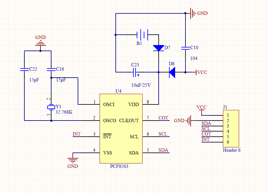
模块原理图
应用
我们将用arduino驱动PCF8563实时时钟模块制作一个闹钟,当时间到后,蜂鸣器响,LED亮起。
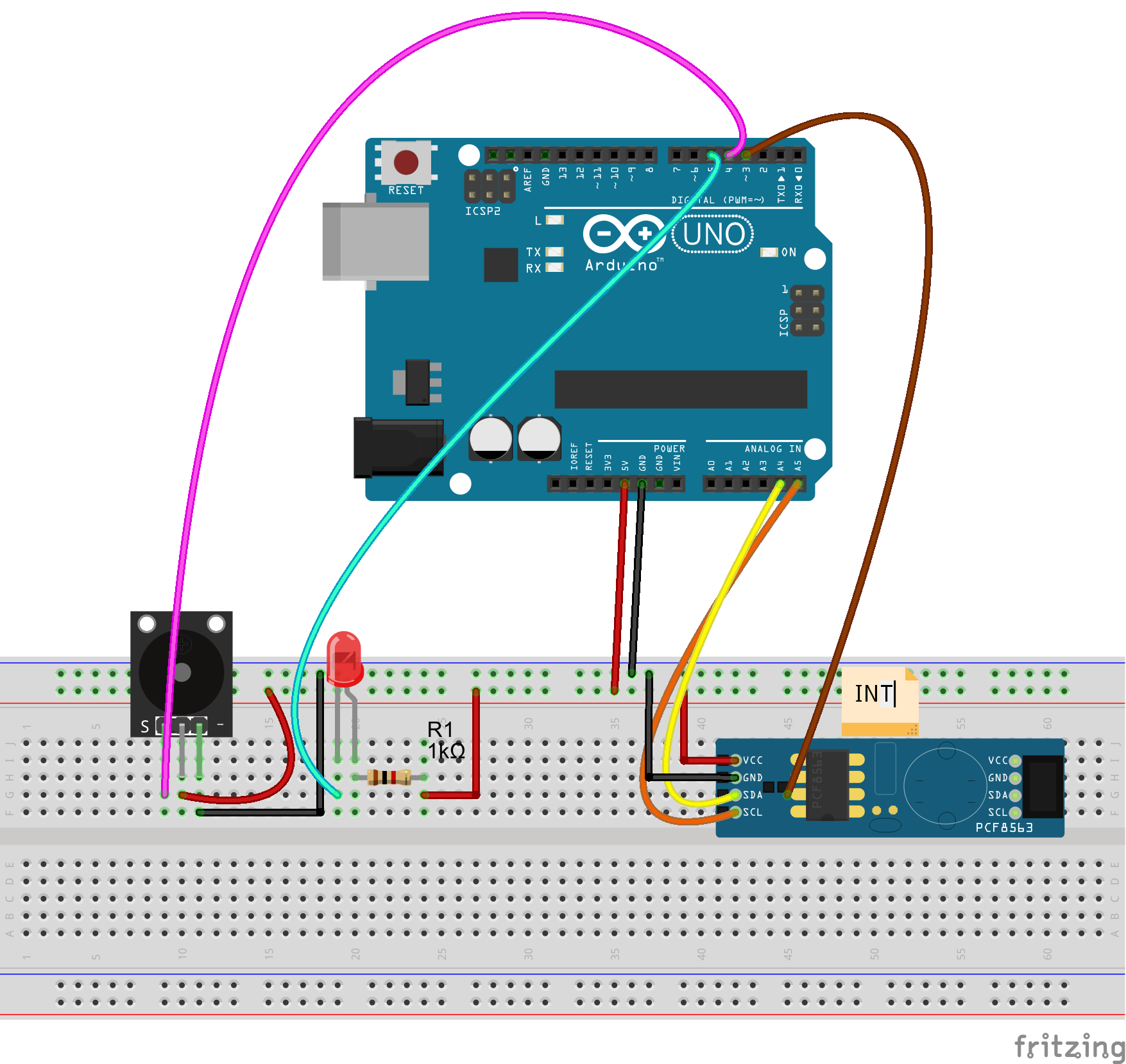
电路连接图
软件
1.安装库文件
下载PCF8563实时时钟模块需要的arduino库文件,下载rtc_pcf8563.zip,解压后放到arduino IDE安装目录下的\libraries目录下
2.示例代码
下载闹钟示例代码arlm.zip,解压后用arduino IDE打开arlm.ino,下面对部分代码作简要说明。
#include < Wire.h >
#include < Rtc_Pcf8563.h >
#define INT 3
#define BEEP 4
#define LED 5
添加相关库文件,定义pcf8563模块中断引脚与arduino uno的D3连接在一起,D3是arduino uno的外部中断1;将蜂鸣器和led分别到D4、D5口上。
volatile int alarm_flag=0;
当闹钟中断标志,当闹钟中断产生时候将alarm_flag置1.
Rtc_Pcf8563 rtc;
实例化一个pcf8563对象
 /* setup int on pin 3 of Arduino */
  attachInterrupt(1, task, FALLING);
  /* clear out all the registers */
  rtc.initClock();
  /* set a time to start with.
   * day, weekday, month, century, year */
  rtc.setDate(1, 5, 9, 0, 17);
  /* hr, min, sec */
  rtc.setTime(10, 56, 55);
  /* set an alarm for 20 secs later...
   * alarm pin goes low when match occurs
   * this triggers the interrupt routine
   * min, hr, day, weekday
   * 99 = no alarm value to be set
   */
  rtc.setAlarm(57, 99, 99, 99);
在setup()函数中,完成了下面几件事
- attachInterrupt(1, task, FALLING),初始化外部中断1,当闹钟时间到后,PCF8563模块会产生低电平信号,平时输出高电平。当闹钟时间到达后,PCF8563模块会产生一个下降沿中断信号,这个下降沿中断信号会触发arduino外部中断,arduino进入中断服务函数task中,执行闹钟和亮灯操作。
- rtc.initClock(),初始化PCF8563内部寄存器,将它们清零。
- rtc.setDate(1, 5, 9, 0, 17),设置日历,根据实际设置。
- rtc.setTime(10, 56, 55),设置时间。
- rtc.setAlarm(57, 99, 99, 99),设置闹钟时间,99表示忽略该参数。
 void task()
{
  digitalWrite(LED,LOW),digitalWrite(BEEP,LOW);//open beep and led
  alarm_flag = 1;
}
task是闹钟中断服务函数,触发中断后将会执行这个函数,这个函数负责点亮LED和让蜂鸣器响,并将alarm_flag标志位置1.
 void clr_alarm()
{
  detachInterrupt(1);
  digitalWrite(LED,HIGH),digitalWrite(BEEP,HIGH);//close beep and led
  rtc.clearAlarm();
  delay(1000);
  alarm_flag=0;
  attachInterrupt(1, task, FALLING);
}
上面的函数用于清除闹钟中断,关闭LED和蜂鸣器,并将alarm_flag标志清0
测试
step 1 用USB线把PC和arduino uno连接起来,选择正确的板卡型号和端口号,烧录到arduino
step 2 打开Serial Monitor将会输出实时时间,当时间到后蜂鸣器和LED会打开3s再关闭。


