Content
- Introduction
- Preparations
- About the 0.96″ 128×64 pixel I2C OLED Display
- Examples
Introduction
When you need to read the output of a DIY electronic device and a laptop, a small display may be the solution. In this lesson, we will show what a 128×64 pixel monochrome I2C OLED display is, and how to use it with the Arduino board.
Preparations
Hardware
- Osoyoo UNO Board (Fully compatible with Arduino UNO rev.3) x 1
- 0.96″ 128×64 pixel I2C OLED Display x 1
- Potiometer x 1
- Jumpers
- USB Cable x 1
- PC x 1
Software
About the 0.96″ 128×64 pixel I2C OLED Display
OLED Display Overview
An Organic Light Emitting Diode(OLED) is a display device which has self light-emitting technology composed of a thin, multi-layered organic film placed between an anode and cathode. In contrast to LCD technology, OLED does not require a back-light.OLED offers wide viewing range, almost 180 degree from left to right and up to down and also consumes less power than existing LCD’s.OLEDs have been used in television screens,computer monitors,mobile phones,Personal Digital Assistants,etc.In the following,OLED with two different types of interfaces are discussed.
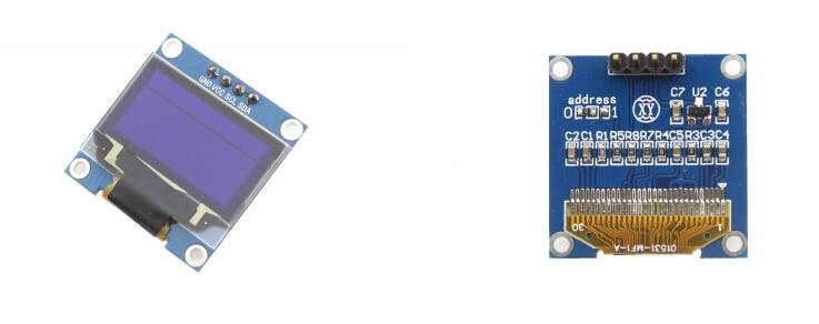
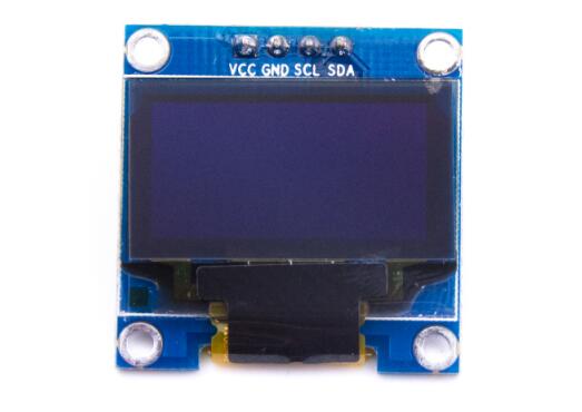
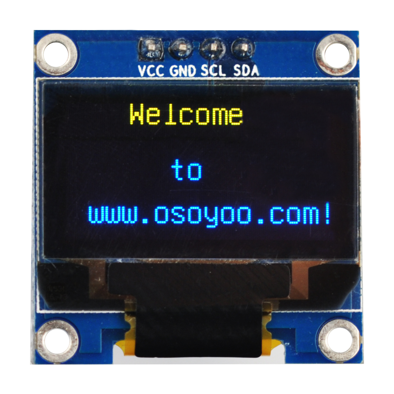
OLED I2C Module
These displays are small, only 0.96″ diameter, but very readable due to the high contrast of an OLED display. This display is made of 128×64 individual white OLED pixels, each one is turned on or off by the controller chip. No back-light is required for this display because it makes its own light which reduces the power required to run the OLED. Its Visual Angle is greater than 160°. It needs only 2 I/O Port to Control,since this display uses the I2C common interface for easy plug and play usage – meaning you can connect it without the need for wires – just plug it straight in to your device.
The screen comes with a nice screen protector with a tab to easily remove it after installation. The PCB is prepared with 4 reasonable-sized holes in the corners for fixation and a 4 pin header already installed for powering and communicating with the display. It can be connected directly to an Arduino without any additional parts.
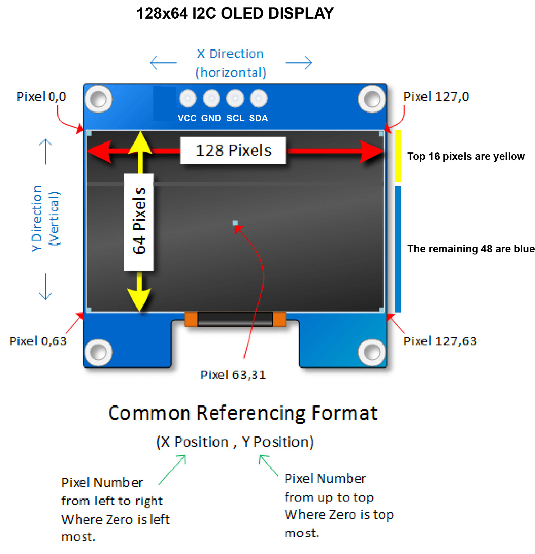
Your Display – Width and Height, X and Y
When you purchased your display, it was offered with a resolution that was expressed by something like “128 x 64”. That description tells you the number of pixels (or tiny LEDs) across and the number of pixels down.
In the case of a ‘128 x 64’ display, it means we have 128 pixels going from left to right, and 64 pixels going up and down. In other words there are 8192 total pixels in a display of this type.
The OLED displaywe are using is a bit different than others because the top 16 pixels are yellow and the remaining 48 are blue. There’s also an approximately 2 pixels high gap between the two parts of the screen so you’re basically forced to use the top part for a different purpose for example as a status bar. Please very notice that this is a single color OLED indeed, that means that top quarter is yellow, and the rest ¾ is blue. The color can not be changed.

This is important because nearly everything you will draw on your display will require you to reference these tiny LEDs known as pixels. You will reference these pixels by first identifying it’s position horizontally ( or the X position) and it’s position vertically (or Y Position). These pixels are numbered as follows:
- Pixels going across the width of the display begin with the zero. In the case of a display that is 128 pixels wide, the numbering begins with zero and ends with 127. Zero is in the columns of left most pixels and 127 is in the column of right most pixels.
- Pixels going up and down, also begin with zero. In the case of a display that is 64 pixels high, numbering begins with zero and ends with 63. Zero is in the row of top pixels and 63 is in the row of bottom pixels.
- Pixels are generally referenced in the format (x,y) where x is the pixel number in the horizontal direction and y is the number in the vertical direction.
Take a moment and study the drawing below.
Features:
It’s a 0.96″ 128X64 OLED, I2C (or IIC) interface, with SSD1306 driver, 3.3/5V compatible.
- A simplified manufacturing process compared to TFT-LCD
- Self-emitting light, in contrast to the required backlight for TFT-LCD
- High luminosity
- Lightweight and thin
- Capable of wide viewing angles>160
- Low operating voltage and power consumption
- Quick response (< second level)
- Wide range of operating temperatures (-30c to 70c)
Specifications:
- High resolution: 128 * 64
- Viewing angle:> 160 degree
- Supports many control chip: Fully compatible with Arduino, 51 Series, MSP430 Series, STM32 / 2, CSR IC, etc.
- Ultra-low power consumption: full screen lit 0.08W
- Voltage: 3V ~ 5V DC
- Working Temperature: -30 c ~ 70 c
- Module Size: 27.0MM * 27.0MM * 4.1MM
- I2C/IIC Interface, need 2 IO only.
- Driver IC: SSD1306
- Character Colour: Yellow and Blue
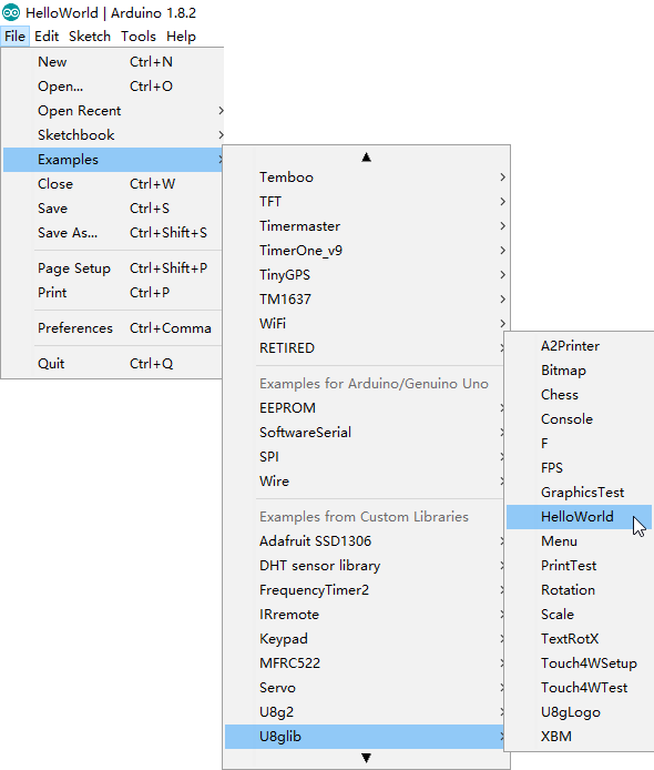
Install library U8glib.h
For this project we will use a library called U8glib.h, which is pretty much kind of a universal driver for driving various LCDs and OLEDs on Arduino and other microcontrollers/embedded platforms. Download Arduino U8glib library first. (If you are using Arduino/Genuino 101, please use U8g2 library) The following link is about How to install Libraries in Arduino IDE.
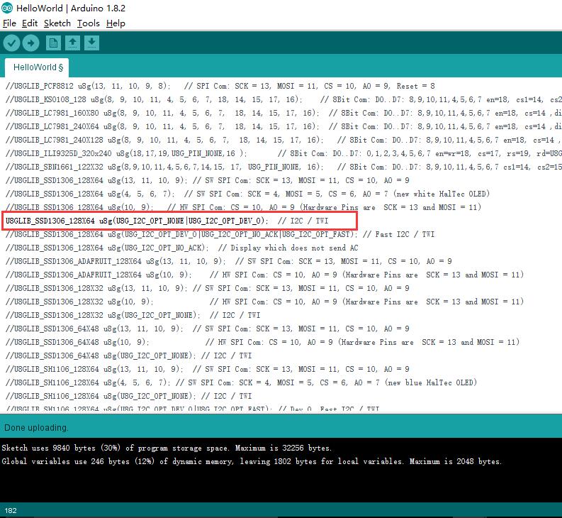
You can find many examples on this library folder, such as below:
We are use the 0.96″ 128X64 I2C OLED display in this tutorial, so uncomment the code (line 88) before you upload the demo sketch to the Arduino board :
U8GLIB_SSD1306_128X64 u8g(U8G_I2C_OPT_NONE);
Examples
“Hello World” by 0.96″ 128×64 I2C OLED display
In this example,we will show how to simply light an I2C OLED display by using an Osoyoo UNO board.
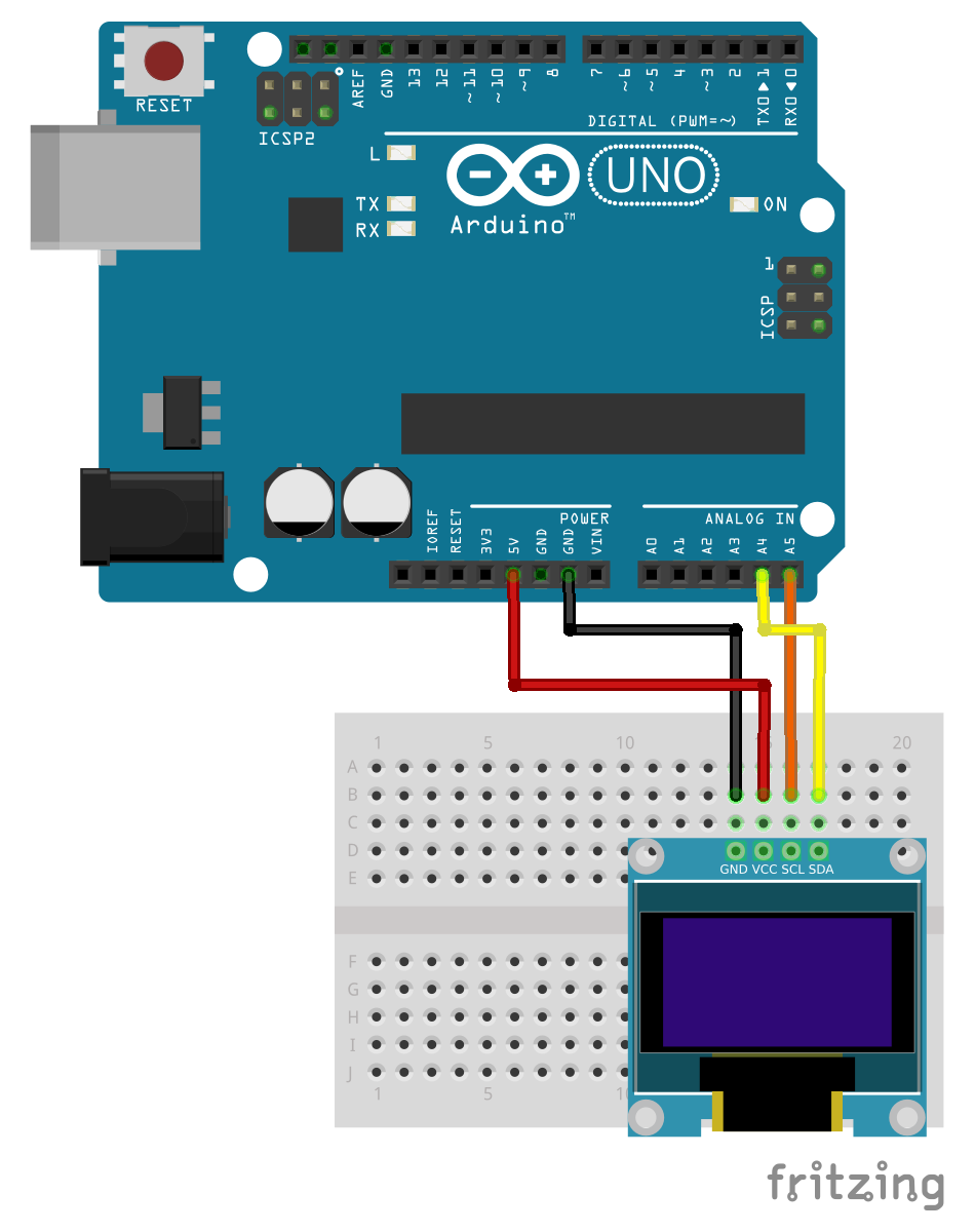
Connection
Before you write the code you have to build the circuit. To do this, connect the pins as follows:
| Osoyoo UNO |
LCD1602 |
| GND |
GND |
| 5V |
VCC |
| A4 |
SDA |
| A5 |
SCL |
Note:
- For Mega2560: the I2C connections are on SDA=20 and SCL=21. So go ahead and wire these up, along with the two power leads to the 5V and GND terminals.
- For Arduino Leonardo: connect SDA to digital pin 2 and SCL to digital pin 3 on your Arduino.
From sketches of Fritzing, you can look at the connections to be done in a simpler way:
Code Program
After above operations are completed, connect the Arduino board to your computer using the USB cable. The green power LED (labelled PWR) should go on.Open the Arduino IDE and choose corresponding board type and port type for you project. Then load up the following sketch onto your Arduino.
#include "U8glib.h"

U8GLIB_SSD1306_128X64 u8g(U8G_I2C_OPT_NONE|U8G_I2C_OPT_DEV_0);  // I2C / TWI

void draw(void) {
  // graphic commands to redraw the complete screen should be placed here
  u8g.setFont(u8g_font_unifont);
  //u8g.setFont(u8g_font_osb21);
  u8g.drawStr( 30, 10, "Hello!");
  u8g.drawStr( 50, 35, "by");
  u8g.drawStr( 10, 56, "www.osoyoo.com");
}

void setup(void) {
  // flip screen, if required
  // u8g.setRot180();

  // set SPI backup if required
  //u8g.setHardwareBackup(u8g_backup_avr_spi);

  // assign default color value
  if ( u8g.getMode() == U8G_MODE_R3G3B2 ) {
    u8g.setColorIndex(255);     // white
  }
  else if ( u8g.getMode() == U8G_MODE_GRAY2BIT ) {
    u8g.setColorIndex(3);         // max intensity
  }
  else if ( u8g.getMode() == U8G_MODE_BW ) {
    u8g.setColorIndex(1);         // pixel on
  }
  else if ( u8g.getMode() == U8G_MODE_HICOLOR ) {
    u8g.setHiColorByRGB(255,255,255);
  }
}

void loop(void) {
  // picture loop
  u8g.firstPage();
  do {
    draw();
  } while( u8g.nextPage() );

  // rebuild the picture after some delay
  delay(50);
}
Basic Program Flow – The Picture Loop
In ‘setup’ we first select the font we want to use. The library supports many different fonts and we will experiment with another later.
After selecting the font, we establish that drawing something means that we want to turn a pixel on. We did this with ‘u8g.setColorIndex(1)‘.
The U8glib graphic library uses something called a picture loop. The picture loop begins with ‘u8g.firstPage()‘ and ends with ‘u8g.nextPage()‘.
The picture loop is a requirement within the graphics library.
Within this picture loop, you can use a variety of graphics commands. In our loop we make a call to ‘draw()‘. In this function we instruct the display to print ‘Hello World’.
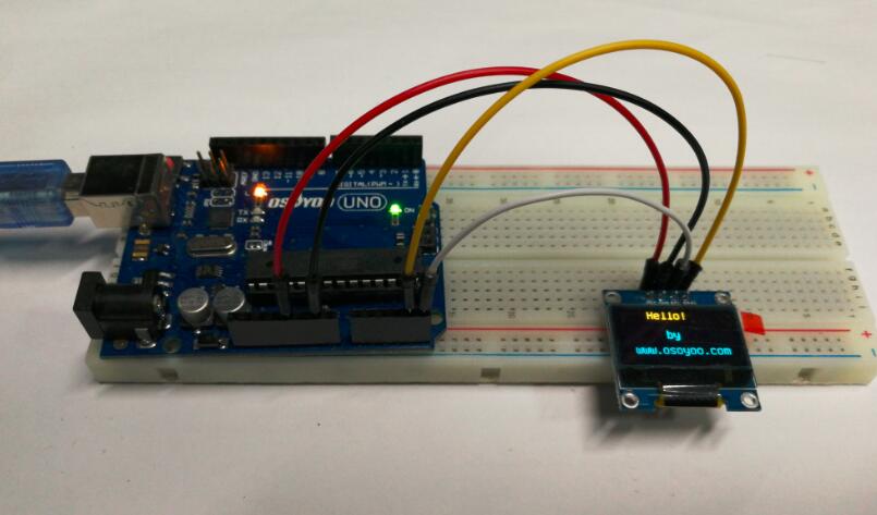
Running Result
A few seconds after the upload finishes, you can see the OLED displays as the first picture in this example.
Scrolling Hello World
As mentioned, being able to set coordinates outside the view screen is useful when you want to animate. One from of animation is to scroll text. Lets try it.
The connection is same as above example, copy and paste the sketch below into your Arduino program. Remember to change your constructor.
#include "U8glib.h"

//**************************************************
// Change this constructor to match your display!!!
U8GLIB_SSD1306_128X64 u8g(U8G_I2C_OPT_NONE|U8G_I2C_OPT_DEV_0);
//**************************************************

int yPos = 0;

void setup() {

  u8g.setFont(u8g_font_unifont);
  u8g.setColorIndex(1); // Instructs the display to draw with a pixel on.
}

void loop() {
  u8g.firstPage();
  do {
    draw();
  } while( u8g.nextPage() );

  // If its too fast, you could add a delay
  if(yPos < 83){
    // if it's too slow, you could increment y by a greater number
    yPos++;  }
  else{
    // When the yPos is off the screen, reset to 0.
    yPos = 0;
  }
}
void draw(){
  u8g.drawStr( 0, yPos, "Hello World");
}
Running Result
A few seconds after the upload finishes, it should look like this:
Part of the magic here has to do with the picture loop (which will be examined in more detail later). But suffice to say, the loop erased the previous display and and created a new display every cycle.
Take a minute and study the code. Tinker with it. Instead from top to bottom, try scrolling from bottom to top. Now try to tinker with the X position and move the display from left to write.


