In this lesson, we will make a complex Capstone project which will use many of our previous knowledge. We will make two groups of sensors and actuators installed on two MEGA-IoT shields (to make things simple, we call Device A and Device ). We also need use ArduinoJson Library which can use short string to transfer data through json format.
The project has following functions:
Device A has DHT 11 temperature sensor which will send data to Device B and display temperature/humidity value in 1602 LCD in Device B.
Device A has Gas Sensor which will send data to Device B . If Gas is detected , buzzer in Device B will alarm.
Device A has RFID module which can send IC card ID to Device B 1602 LCD .
Device B has Red LED which can be turned on/off by push buttons in Device A.
OSOYOO Advanced Board for Arduino MEGA2560 x 2
OSOYOO MEGA-IoT extension board x 2
USB Cable x 2
Red LED PnP module x 2
Push Button PnP Module x 2
I2C 1602 LCD PnP module x 1
Gas detection PnP module x 1
RFID modules x 1
Buzzer PnP module x 1
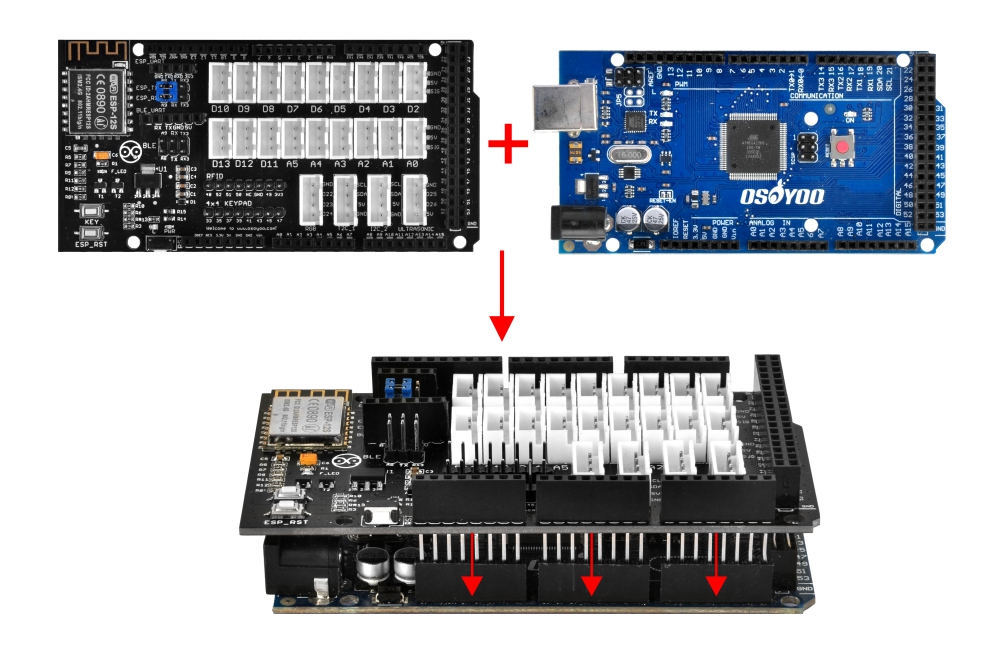
First please plug OSOYOO MEGA-IoT Extension Board into OSOYOO Advanced Board for Arduino MEGA2560:
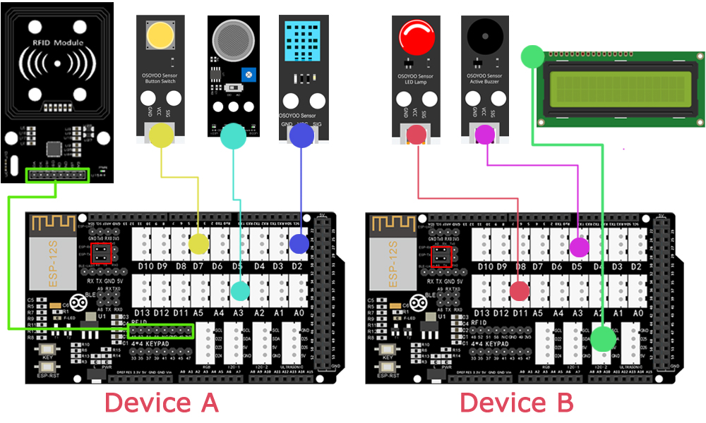
Then connect the modules with two OSOYOO MEGA-IoT Extension Boards (Device A&Device B) with PnP cables as below.
(Jumper Cap should connect ESP8266 RX with A8, TX with A9)
Modules – Device A
DHT11 – D2
RFID Module – RFID
Gas Sensor – A3
Push Button Module – D7
Modules – Device B
1602 LCD Module – I2C
Buzzer Module – D5
Red LED Module – D11
Notice: Shut off your battery or Unplug your power adapter when upload sketch code to OSOYOO Advanced Board for Arduino MEGA2560.
Please be noted that in this lesson, you need two pcs of Osoyoo Mega-IoT extension shields,mega 2560 and devices (Device A and Device B).
Step 1 Install latest IDE (If you have IDE version after 1.1.16, please skip this step).Download IDE from https://www.arduino.cc/en/software, then install the software.
step2 WifiEsp Library Installation (if you have installed WifiESP library, please skip this step)
OSOYOO MEGA-IoT extension TX/RX pin to OSOYOO Advanced Board for Arduino MEGA2560 A9/A8 pin by default. So in sketch code, we need use Software Serial Port to communicate with ESP8266 (set A9 as TX and A8 as RX in softwareserial object).
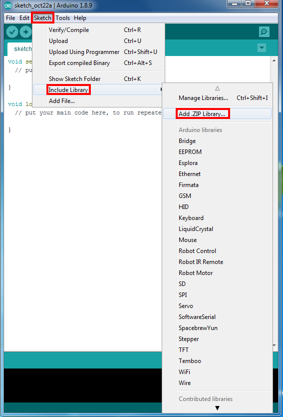
Open IDE ->Sketch ->Include Library ->Add ,Zip library to load above zip files into IDE. Step 5 After installing above library, please download the main code from following link.unzip the download zip file lesson19.zip, you will see a folder called smarthome-lesson19.https://osoyoo.com/driver/smarthome/smarthome-lesson19.zipUnzip the downloaded zip file, you will see two sub-folders in smarthome-lesson19: deviceA and deviceB
Step 6 After above operations are completed, connect OSOYOO MEGA2560 Boards to PCs with USB cables.
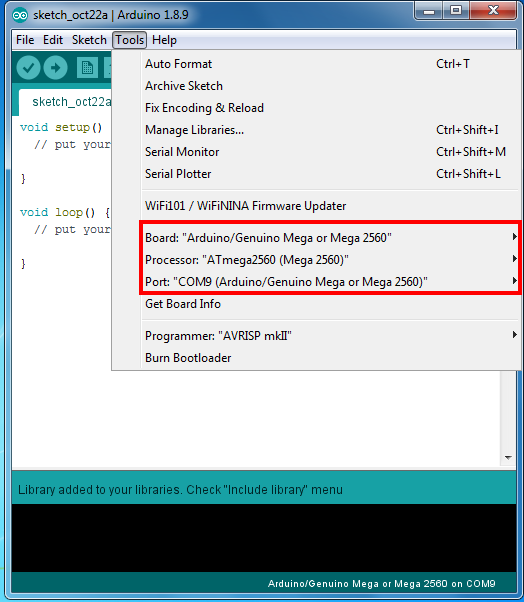
Step 7 Open the IDE and choose corresponding board type and port type for you project.Step 8 IDE: Click file -> click Open -> choose code “smarthome-lesson19”, load up sketch in folder deviceA to Device A and sketch in deviceB folder to device B.
Note:
In sketch deviceA, you need change WIFI SSID and password in Line 28,29, you also need set device B IP address in line 32.
In sketch deviceB, you need change WIFI SSID and password in Line 22,23, you also need set device A IP address in line 26.
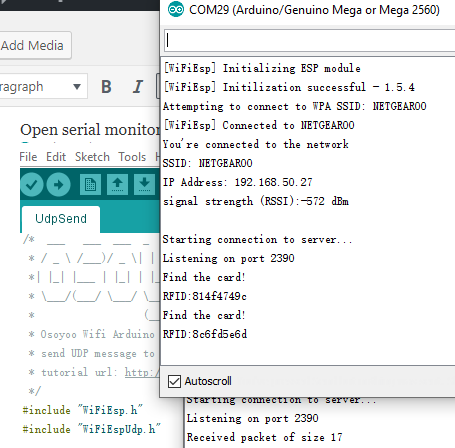
Step 1) please load deviceA.ino to Sender device.
Make sure have changed line 22,28,32 with correct wifi password,ssid and device B IP address.
If you don’t know receiver device IP address, you need run sample code in lesson 3
Open serial monitor, put a IC card to RFID module, you will see following screen:
As receiver sketch is not running, you can not get any action at this moment.
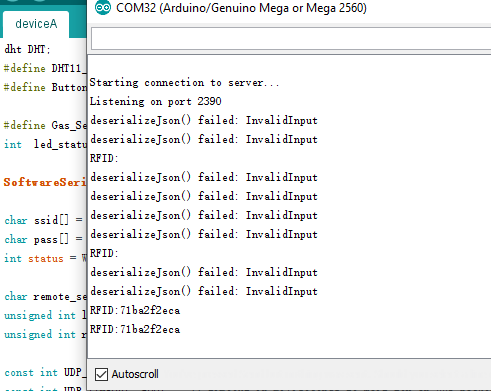
Step 2) please load deviceB.ino to device B board, also change the wifi ssid ,password and device A Ip address properly.
Open serial monitor, you will see following screen:
At the beginning , there is some error because no IC card detected in device A. After you Put an IC card to device A RFID moduel, it will show RFID number in serial monitor.
Now check the LCD which is connected to I2C 1 slot of Device B, it will show Temperature, Humidity and RFID# which is sent from Device DHT11 sensor and RFID module.
Red LED in Device B which can be turned on/off by push buttons in Device A.
let’s use a gas lighter to leak some gas to gas sensor, buzzer in Device B will alarm.
You can add some more sensors and actuators in this project and make far more complex IoT projects. If you have any question, feel free to contact [email protected] to get help.


 Step 8 IDE: Click file -> click Open -> choose code “smarthome-lesson19”, load up sketch in folder deviceA to Device A and sketch in deviceB folder to device B.