In this lesson, we will learn how to program a gyroscope with Arduino to optimize the Espro 2WD Robot Car’s performance.
This tutorial focuses on enhancing the Espro 2WD Robot Car’s ability to drive straight by using the MPU6050 Inertial Measurement Unit (IMU). The MPU6050, a 3-axis motion tracking device, provides angular velocity (gyroscope) and linear acceleration (accelerometer) data, enabling the robot to actively correct its heading. This lesson covers sensor fusion techniques and PID control algorithms for robust straight-line performance.
You must complete lesson 1 before you continue on with this lesson1.
OSOYOO ESPro Robot car chassis x1
OSOYOO Wheels x2
OSOYOO DC motors x2
OSOYOO ESPro motor driver board x1
OSOYOO Voltage meter x1
OSOYOO MPU6050 Gyro Module x1
OSOYOO Battery box x1
OSOYOO 3pin female to female jumper wire x1
OSOYOO 4pin female to female jumper wire x1
18650 Batteries (3.7 V) x2
Battery charger x1
Step1: Complete the basic hardware assembly as described in robot car Lesson 1. If you already finished Lesson 1, just keep everything as is.
Step 2: Mount the MPU6050 module securely on the robot chassis as shown below. (The MPU6050 communicates with the Arduino via the I2C protocol, which requires only two data lines: SDA (Serial Data) and SCL (Serial Clock), plus power (VCC) and ground (GND).
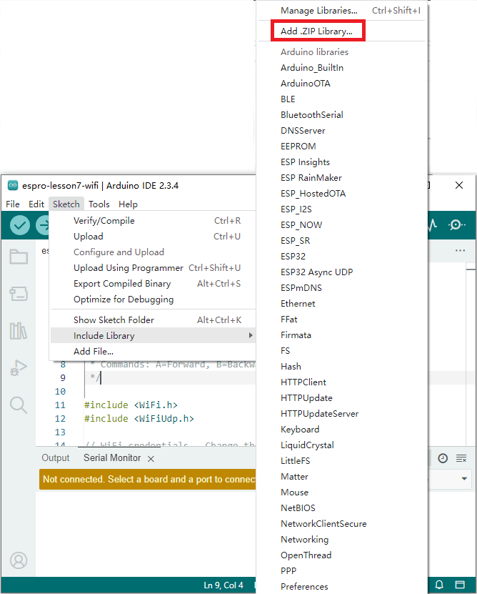
In Arduino IDE top menu -> Sketch ->Include Library->Manage Libraries
Search MPU6050_light , you will find a library “MPU6050_light by rfetick”,
Click Install, then to install MPU6050_light library.
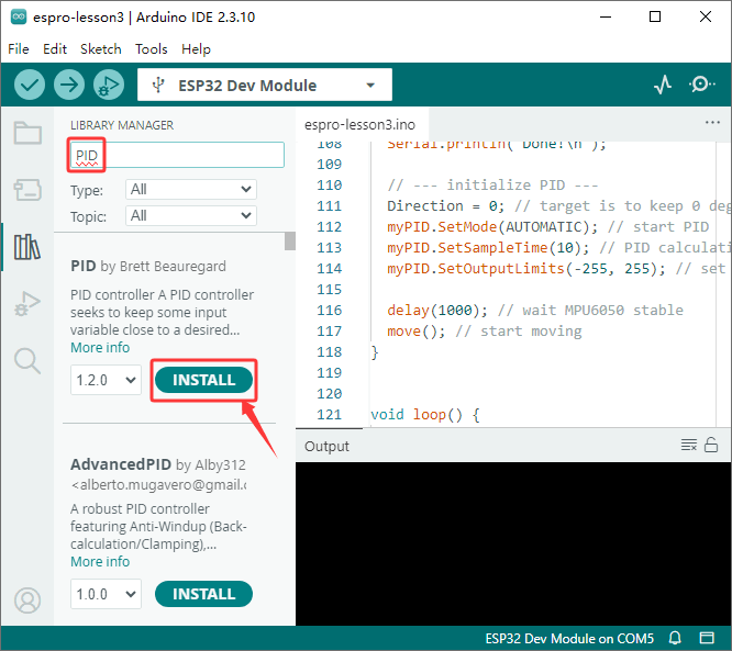
Similarly, install PID library from Arduino IDE as following :
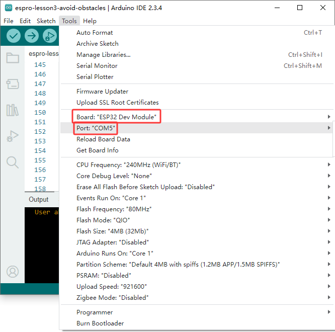
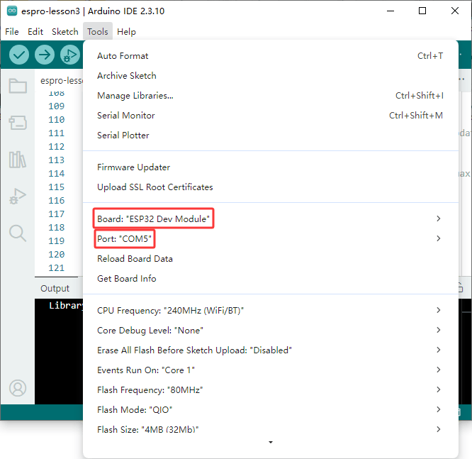
Step 4. Board and Port Selection
Connect the ESPro motor driver board to your computer via a USB cable (Important: make sure the robot car’s power switch is OFF and the battery is disconnected before connecting the board to your PC), Last select correct port which matches ESP32 board,upload the sketch to the board, upload the Code.
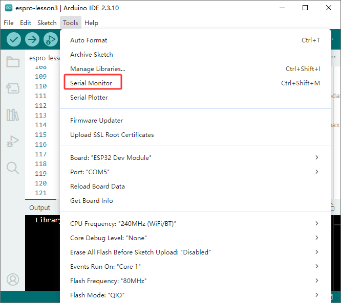
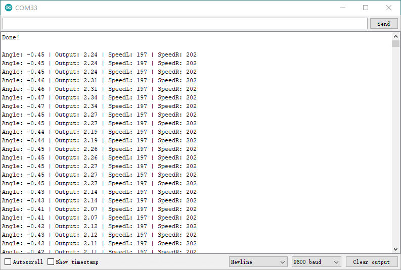
In Serial Monitor, set baud rate to 9600, then you should see:
MPU6050 Found!
Step 5.Check Whether Arduino Detects the MPU6050
Open the Serial Monitor (top-right corner of the Arduino IDE), set the baud rate to 9600, and you should see MPU6050 Found! as shown below. Congratulations! The Arduino is detecting the MPU6050 — you are ready to test the car.
Congrats! This means Arduino detects MPU6050 and you can put the car in the ground and test the performance.
Now you can put the car onto the ground, turn on the power. You will see the car will stay freeze for a while waiting the Arduino to initialize the gyro. Then the car will move straight forward . If you use your foot to force the car change direction, the car will automatically go back to its original direction.
A Brief Explanation to the Principle and Arduino code .
1) How does the Move() function control the car’s movement and steering?
The OSOYOO robot car used in this lesson utilizes differential steering. The move(speedL, speedR) function has two parameters, speedL and speedR, which represent the rotational speed of the car’s left and right wheels, respectively. The speed value ranges from -255 to +255, where a positive value indicates forward rotation and a negative value indicates backward rotation. For example, move(-50, 100) means the left wheel rotates backward at a speed of 50, while the right wheel rotates forward at a speed of 100. In this case, the car should make a sharp left turn.
2) MPU6050 Coding Introduction
After initialization, the gyroscope MPU6050 can consistently determine its orientation relative to its starting direction. When our robot car moves and deviates from this initial direction, the MPU6050 reports the amount of this deviation back to the Arduino.
In our code, the Direction variable represents the car’s orientation at the moment it was placed on the ground (we assume it’s facing forward, so we set Direction to 0).
After the calculations in the first few lines of the loop() function, we obtain the car’s current orientation in the currentAngle variable on line 129.
3) Introduction about PID and Code:
The Big Idea: What is PID?
Imagine you are driving a car and your goal is to keep it perfectly in the center of your lane. That’s what we’re asking our robot to do: stay on the “straight ahead” line.
PID is a control algorithm that acts like a smart, attentive driver. It continuously asks three questions to decide how to steer:
P (Proportional): How far am I from the center of the lane right now?
I (Integral): Have I been consistently off-center for the past few moments?
D (Derivative): Am I swerving towards or away from the center too quickly?
By combining the answers to these three questions, the PID controller makes a smooth and efficient steering correction.
How the PID Function Works in Our Code
Let’s connect this theory directly to the PID_v1.h library and your code.
1. Initialization (in setup()):
// We tell the PID controller what to watch and what to control.PID myPID(&Input, &Output, &Setpoint, Kp, Ki, Kd, DIRECT);Direction = 0; // Our TARGET is to have an angle of 0 degrees.myPID.SetMode(AUTOMATIC); // Turn on the controller.
&Input: This is a pointer to our sensor reading. In our code, Input is currentAngle. The PID controller will constantly read this value.
&Output: This is a pointer to our result. The PID controller will write its final calculated correction value into the Output variable.
&Direction: This is a pointer to our target. We want to stay straight, so we set this to 0.
2. The Magic (in loop()):
// 1. We get the sensor reading and put it into the Input variable.Input = currentAngle; // 2. We call the compute function. This is where the PID magic happens!myPID.Compute(); // 3. We use the result to control the motors.int speedL = baseSpeed - Output;int speedR = baseSpeed + Output;move(speedL, speedR);
The myPID.Compute() function does all the hard work internally. Every time it’s called (the library handles the timing based on SetSampleTime), it:
Reads the value from the Input variable (currentAngle).
Calculates the error: error = Direction - Input.
Calculates the Proportional term (Kp * error).
Calculates and adds the Integral term (Ki * accumulated_error).
Calculates and adds the Derivative term (Kd * rate_of_error_change).
Sums them all up to get the final correction value.
Writes this final value into the Output variable.
So, if Output is +15, it means the robot needs a correction of “15 units.” We apply this by slowing down one motor (baseSpeed - 15) and speeding up the other (baseSpeed + 15), causing the robot to turn and reduce its error. If the robot is perfectly straight, Input will be 0, the error will be 0, and Output will be 0, so both motors will run at baseSpeed.
How to Adjust Kp, Ki and Kd value to make car moving stable
MUST DO: Modify your code to set Ki = 0.0 and Kd = 0.0.
Find a Kp value that is stable and doesn’t oscillate (or barely oscillates). This will likely be lower than 1.5.
(Optional but recommended) Add a deadband of around 0.5 degrees to your loop to ignore sensor noise.
Once Kp is stable, slowly add Kd to dampen any remaining overshoot.
Finally, slowly add Ki to eliminate any long-term, steady drift.