In this lesson, we’ll show how to control SG90 servo using Raspberry Pi.
Hareware Preparation
1 * Raspberry Pi
1 * Breadboard
1 * SG90 servo motor
1 * PCA9685
1 * Breadboard power supply
Jumper wires
1 * T-Extension Board
1 * 40-Pin Cable
Software Preparation Note: In this lesson, we remotely control raspberry pi via PuTTy on PC. To learn how to config raspberry pi, please visit lesson 1: getting started with raspberry pi.
Work principle
A SG90 is a servo which can rotate approximately 180 degrees. It consists of a DC-motor, position system and gears. there are three wires: the red wire is connected to power, the brown wire is connected to Ground, the yellow wire is connected to PWM Signal. The rotate angle is determined by the equation:
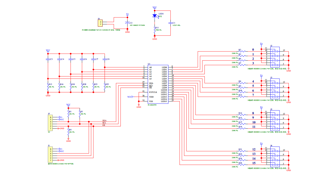
In this project, we use a PCA9685 16-channel servo motor driver module to control the Dutycycle. The PCA9685 module is an i2c-controlled PWM driver, it uses only two pins to control 16 PWM outputs. You can chain up 62 same modules on a single i2c at once. That means can control up to total of 992 outputs. the PCA9685 work frequence is adjustable from 24Hz to 1526Hz, the dutycycle is adjustable from0% to 100%, for PCA9685 datasheet, please visit here:datasheet
Schematic diagram as followed:
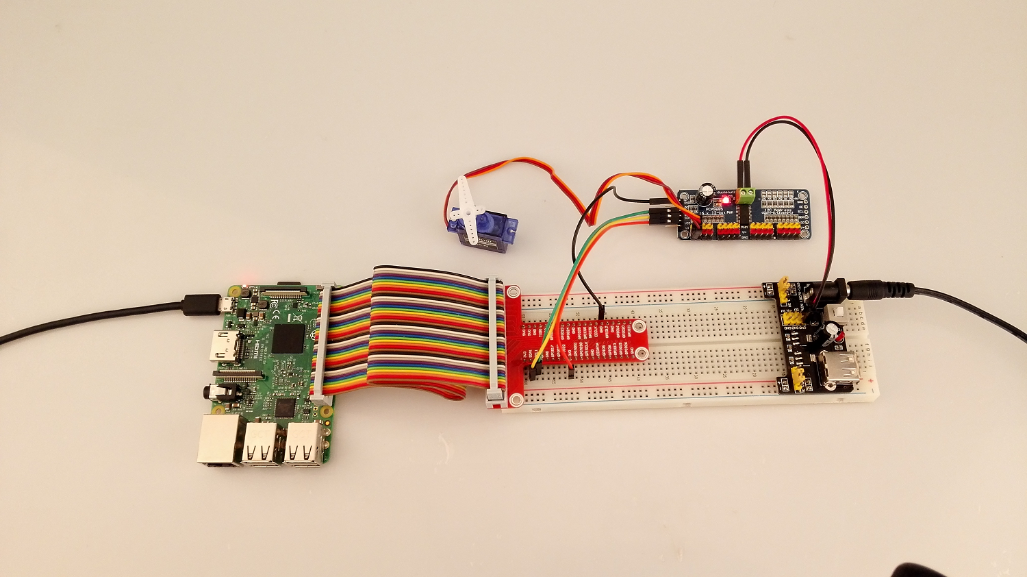
Hardware Setup
Sample code
Before running program, please config the Pi as followed steps:
1) Enable I2C(if you have done, please skip)
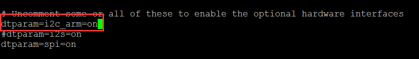
sudo nano /boot/config.txt
open the file /boot/config.txt, find the code line”dtparam=i2c_arm”,checking if there is # sign in front of the line, uncomment it (remove the # in front of this line), finally the code should looks like this:
2) Load IIC Modules(if you have done, please skip)
sudo nano /etc/modules
open /etc/modules file,Add these two lines as below:
i2c-bcm2708
i2c-dev
3) Reboot Pi
reboot
for C language users
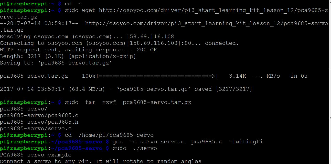
1 ) Download and unzip the sample code file pca9685-servo.tar
Once the program is running, it will rotate to a random angles. Sample code and analysis comments:
#include "pca9685.h"
#include < wiringPi.h>
#include < stdio.h>
#include < stdlib.h>

#define PIN_BASE 300
#define MAX_PWM 4096
#define HERTZ 50

/**
 * Calculate the number of ticks the signal should be high for the required amount of time
 */
int calcTicks(float impulseMs, int hertz)
{
      float cycleMs = 1000.0f / hertz;
      return (int)(MAX_PWM * impulseMs / cycleMs + 0.5f);
}

/**
 * input is [0..1]
 * output is [min..max]
 */
float map(float input, float min, float max)
{
      return (input * max) + (1 - input) * min;
}


int main(void)
{
      printf("PCA9685 servo example\n");
      printf("Connect a servo to any pin. It will rotate to random angles\n");

      // Setup with pinbase 300 and i2c location 0x40
      int fd = pca9685Setup(PIN_BASE, 0x40, HERTZ);
      if (fd < 0) { printf("Error in setup\n"); return fd; } // Reset all output pca9685PWMReset(fd); // Set servo to neutral position at 1.5 milliseconds // (View http://en.wikipedia.org/wiki/Servo_control#Pulse_duration) float millis = 1.5; int tick = calcTicks(millis, HERTZ); pwmWrite(PIN_BASE + 16, tick); delay(2000); int active = 1; while (active) { // That's a hack. We need a random number < 1 float r = rand(); while (r > 1)
                  r /= 10;

            millis = map(r, 1, 2);
            tick = calcTicks(millis, HERTZ);

            pwmWrite(PIN_BASE + 16, tick);
            delay(1000);
      }

      return 0;
}
#include < wiringPi.h >
#include < wiringPiI2C.h >
#include "pca9685.h"
// Setup registers
#define PCA9685_MODE1 0x0
#define PCA9685_PRESCALE 0xFE

// Define first LED and all LED. We calculate the rest
#define LED0_ON_L 0x6
#define LEDALL_ON_L 0xFA

#define PIN_ALL 16


// Declare
static void myPwmWrite(struct wiringPiNodeStruct *node, int pin, int value);
static void myOnOffWrite(struct wiringPiNodeStruct *node, int pin, int value);
static int myOffRead(struct wiringPiNodeStruct *node, int pin);
static int myOnRead(struct wiringPiNodeStruct *node, int pin);
int baseReg(int pin);


/**
 * Setup a PCA9685 device with wiringPi.
 *
 * pinBase:       Use a pinBase > 64, eg. 300
 * i2cAddress:      The default address is 0x40
 * freq:            Frequency will be capped to range [40..1000] Hertz. Try 50 for servos
 */
int pca9685Setup(const int pinBase, const int i2cAddress, float freq)
{
      // Create a node with 16 pins [0..15] + [16] for all
      struct wiringPiNodeStruct *node = wiringPiNewNode(pinBase, PIN_ALL + 1);

      // Check if pinBase is available
      if (!node)
            return -1;

      // Check i2c address
      int fd = wiringPiI2CSetup(i2cAddress);
      if (fd < 0) return fd; // Setup the chip. Enable auto-increment of registers. int settings = wiringPiI2CReadReg8(fd, PCA9685_MODE1) & 0x7F; int autoInc = settings | 0x20; wiringPiI2CWriteReg8(fd, PCA9685_MODE1, autoInc); // Set frequency of PWM signals. Also ends sleep mode and starts PWM output. if (freq > 0)
            pca9685PWMFreq(fd, freq);


      node->fd                  = fd;
      node->pwmWrite            = myPwmWrite;
      node->digitalWrite      = myOnOffWrite;
      node->digitalRead      = myOffRead;
      node->analogRead      = myOnRead;

      return fd;
}

/**
 * Sets the frequency of PWM signals.
 * Frequency will be capped to range [40..1000] Hertz. Try 50 for servos.
 */
void pca9685PWMFreq(int fd, float freq)
{
      // Cap at min and max
      freq = (freq > 1000 ? 1000 : (freq < 40 ? 40 : freq)); // To set pwm frequency we have to set the prescale register. The formula is: // prescale = round(osc_clock / (4096 * frequency))) - 1 where osc_clock = 25 MHz // Further info here: http://www.nxp.com/documents/data_sheet/PCA9685.pdf Page 24 int prescale = (int)(25000000.0f / (4096 * freq) - 0.5f); // Get settings and calc bytes for the different states. int settings = wiringPiI2CReadReg8(fd, PCA9685_MODE1) & 0x7F; // Set restart bit to 0 int sleep = settings | 0x10; // Set sleep bit to 1 int wake = settings & 0xEF; // Set sleep bit to 0 int restart = wake | 0x80; // Set restart bit to 1 // Go to sleep, set prescale and wake up again. wiringPiI2CWriteReg8(fd, PCA9685_MODE1, sleep); wiringPiI2CWriteReg8(fd, PCA9685_PRESCALE, prescale); wiringPiI2CWriteReg8(fd, PCA9685_MODE1, wake); // Now wait a millisecond until oscillator finished stabilizing and restart PWM. delay(1); wiringPiI2CWriteReg8(fd, PCA9685_MODE1, restart); } /** * Set all leds back to default values (: fullOff = 1) */ void pca9685PWMReset(int fd) { wiringPiI2CWriteReg16(fd, LEDALL_ON_L , 0x0); wiringPiI2CWriteReg16(fd, LEDALL_ON_L + 2, 0x1000); } /** * Write on and off ticks manually to a pin * (Deactivates any full-on and full-off) */ void pca9685PWMWrite(int fd, int pin, int on, int off) { int reg = baseReg(pin); // Write to on and off registers and mask the 12 lowest bits of data to overwrite full-on and off wiringPiI2CWriteReg16(fd, reg , on & 0x0FFF); wiringPiI2CWriteReg16(fd, reg + 2, off & 0x0FFF); } /** * Reads both on and off registers as 16 bit of data * To get PWM: mask each value with 0xFFF * To get full-on or off bit: mask with 0x1000 * Note: ALL_LED pin will always return 0 */ void pca9685PWMRead(int fd, int pin, int *on, int *off) { int reg = baseReg(pin); if (on) *on = wiringPiI2CReadReg16(fd, reg); if (off) *off = wiringPiI2CReadReg16(fd, reg + 2); } /** * Enables or deactivates full-on * tf = true: full-on * tf = false: according to PWM */ void pca9685FullOn(int fd, int pin, int tf) { int reg = baseReg(pin) + 1; // LEDX_ON_H int state = wiringPiI2CReadReg8(fd, reg); // Set bit 4 to 1 or 0 accordingly state = tf ? (state | 0x10) : (state & 0xEF); wiringPiI2CWriteReg8(fd, reg, state); // For simplicity, we set full-off to 0 because it has priority over full-on if (tf) pca9685FullOff(fd, pin, 0); } /** * Enables or deactivates full-off * tf = true: full-off * tf = false: according to PWM or full-on */ void pca9685FullOff(int fd, int pin, int tf) { int reg = baseReg(pin) + 3; // LEDX_OFF_H int state = wiringPiI2CReadReg8(fd, reg); // Set bit 4 to 1 or 0 accordingly state = tf ? (state | 0x10) : (state & 0xEF); wiringPiI2CWriteReg8(fd, reg, state); } /** * Helper function to get to register */ int baseReg(int pin) { return (pin >= PIN_ALL ? LEDALL_ON_L : LED0_ON_L + 4 * pin);
}


//------------------------------------------------------------------------------------------------------------------
//
//      WiringPi functions
//
//------------------------------------------------------------------------------------------------------------------


/**
 * Simple PWM control which sets on-tick to 0 and off-tick to value.
 * If value is <= 0, full-off will be enabled * If value is >= 4096, full-on will be enabled
 * Every value in between enables PWM output
 */
static void myPwmWrite(struct wiringPiNodeStruct *node, int pin, int value)
{
      int fd   = node->fd;
      int ipin = pin - node->pinBase;

      if (value >= 4096)
            pca9685FullOn(fd, ipin, 1);
      else if (value > 0)
            pca9685PWMWrite(fd, ipin, 0, value);      // (Deactivates full-on and off by itself)
      else
            pca9685FullOff(fd, ipin, 1);
}

/**
 * Simple full-on and full-off control
 * If value is 0, full-off will be enabled
 * If value is not 0, full-on will be enabled
 */
static void myOnOffWrite(struct wiringPiNodeStruct *node, int pin, int value)
{
      int fd   = node->fd;
      int ipin = pin - node->pinBase;

      if (value)
            pca9685FullOn(fd, ipin, 1);
      else
            pca9685FullOff(fd, ipin, 1);
}

/**
 * Reads off registers as 16 bit of data
 * To get PWM: mask with 0xFFF
 * To get full-off bit: mask with 0x1000
 * Note: ALL_LED pin will always return 0
 */
static int myOffRead(struct wiringPiNodeStruct *node, int pin)
{
      int fd   = node->fd;
      int ipin = pin - node->pinBase;

      int off;
      pca9685PWMRead(fd, ipin, 0, &off);

      return off;
}

/**
 * Reads on registers as 16 bit of data
 * To get PWM: mask with 0xFFF
 * To get full-on bit: mask with 0x1000
 * Note: ALL_LED pin will always return 0
 */
static int myOnRead(struct wiringPiNodeStruct *node, int pin)
{
      int fd   = node->fd;
      int ipin = pin - node->pinBase;

      int on;
      pca9685PWMRead(fd, ipin, &on, 0);

      return on;
}
 #ifdef __cplusplus
extern "C" {
#endif

// Setup a pca9685 at the specific i2c address
extern int pca9685Setup(const int pinBase, const int i2cAddress/* = 0x40*/, float freq/* = 50*/);

// You now have access to the following wiringPi functions:
//
// void pwmWrite (int pin, int value)
//            if value <= 0, set full-off // else if value >= 4096, set full-on
//            else set PWM
//
// void digitalWrite (int pin, int value)
//             if value != 0, set full-on
//            else set full-off
//
// int digitalRead (int pin)
//            read off-register
//            To get PWM: mask with 0xFFF
//            To get full-off bit: mask with 0x1000
//            Note: ALL_LED pin will always return 0
//
// int analogRead (int pin)
//            read on-register
//            To get PWM: mask with 0xFFF
//            To get full-on bit: mask with 0x1000
//            Note: ALL_LED pin will always return 0


// Advanced controls
// You can use the file descriptor returned from the setup function to access the following features directly on each connected pca9685
extern void pca9685PWMFreq(int fd, float freq);
extern void pca9685PWMReset(int fd);
extern void pca9685PWMWrite(int fd, int pin, int on, int off);
extern void pca9685PWMRead(int fd, int pin, int *on, int *off);

extern void pca9685FullOn(int fd, int pin, int tf);
extern void pca9685FullOff(int fd, int pin, int tf);

#ifdef __cplusplus
}
#endif
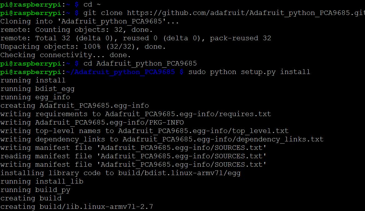
for python user
1) Install python-smbus and i2c-tools(if you have done, please skip)
sudo apt-get install -y python-smbus i2c-tools
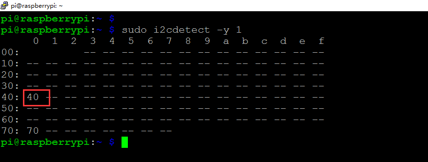
2) To verify if I2C library is installed properly, you can run following terminal command:
sudo i2cdetect -y 1
or port 0 on the older Raspberry Pi
sudo i2cdetect -y 0
Once the program is running, the terminal will display a table like below showing PCA9685 address if any devices are connected, in this example the PCA9685 address is 0 x 40.