Overhere we will show you what is the I2C LCD 1602 Display and how it works, you can follow the next lesson to get how to use the I2C LCD 1602 Display with the micro bit.
Parts Needed You will need the following parts:
1x micro:bit
1x Micro B USB Cable
1x micro:bit Breakout (with Headers)
1x Breadboard
5x Jumper Wires
1x I2C LCD 1602 Display
About I2C LCD 1602 Display
The integration of an LCD display greatly facilitates the interactivity of the project you are developing, allowing the user to directly read some output parameters. These values can be either a simple text or numerical values read by the sensors, such as temperature or pressure, or even the number of cycles that the Arduino is performing.
However, these displays have a small problem. When they are connected to a microcontroller (such as Micro bit for example), these displays require virtually many connection PINs occupying practically almost all available IO and leaving the multiprocessor few outputs for any other devices and sensors. This problem has been solved thanks to the communication on the I2C bus.
The LCD1602 display has an integrated microchip that manages this type of communication, and then all of the input and output information are limited to only two PINs (excluding power supply). I2C is a type of serial bus developed by Philips, which uses two bidirectional lines, called SDA (Serial Data Line) and SCL (Serial Clock Line). Both must be connected via pulled-up resistors. The usage voltages are standard as 5V and 3.3V.
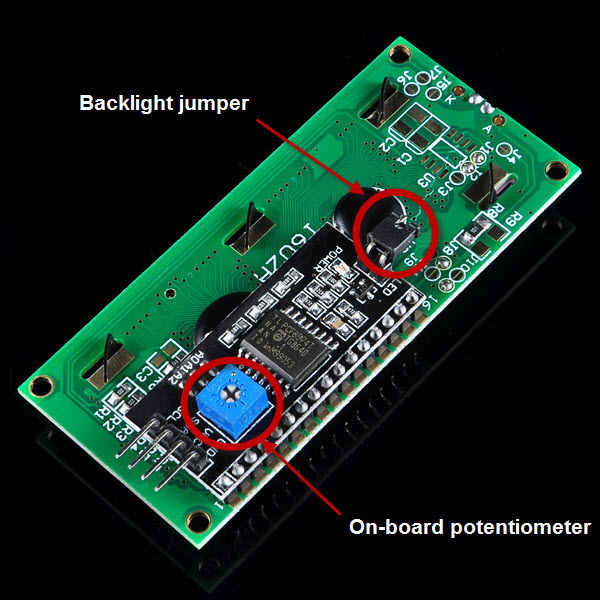
The blue potentiometer on the I2C LCD1602 (see the figure below) is used to adjust the backlight for better display.And there is a jumper on the board, if you take away this jumper , the backlight will aways be off.
Makecode I2C LCD1602 package for micro:bit
usage
open your microbit makecode project, in Add Package, paste
ShowNumber(n: number, x: number, y: number)
show a number in LCD at given position.
n: number will be show
x: is LCD column position, [0 – 15]
y: is LCD row position, [0 – 1]
ShowString(s: string, x: number, y: number)
show a string in LCD at given position.
s: string will be show
x: is LCD column position, [0 – 15]
y: is LCD row position, [0 – 1]
on()
turn on LCD
off()
turn off LCD
clear()
clear LCD content
BacklightOn()
turn on LCD backlight
BacklightOff()
turn off LCD backlight
shl() shift left screen
shr() shift right screen
Demo
License
MIT
Copyright (c) 2018, microbit/micropython Chinese community
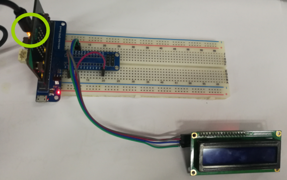
Because the output power of the micro bit is limited, please connect the USB cable to the USB port on the micro bit when downloading the program. After the program is successfully downloaded to the board, connect the USB cable to the USB port on the expansion board, ensure the LCD display can work perfectly.
Run Your Script
If you are not familiar to make code, don’t worry. At first, you can enter this link: https://makecode.microbit.org/reference to get the reference of microbit block.
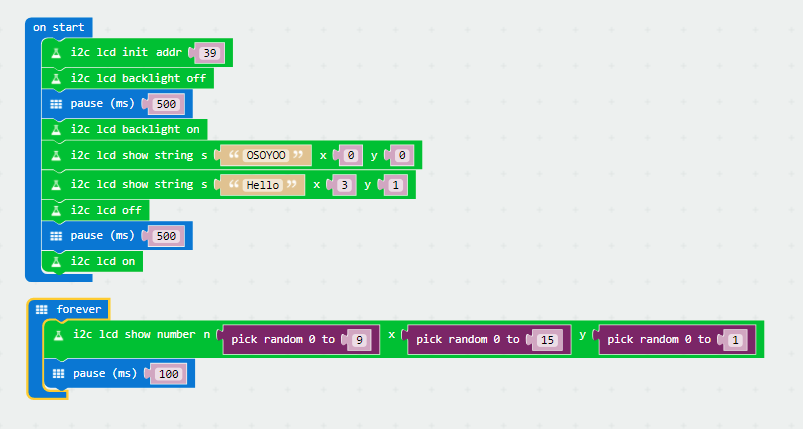
Either copy and paste, or re-create the following code into your own MakeCode editor by clicking the open icon in the upper right-hand corner of the editor window. You can also just download this example by clicking the download button in the lower right-hand corner of the code window.
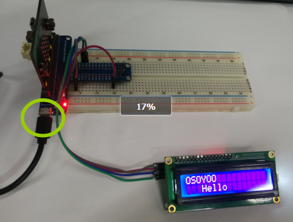
After downloaded this code to your micro bit, pull out the USB line and insert the USB line to the expansion board, you will see “OSOYOO”,”Hello” on the LCD screen, then the entire screen will be full of random numbers.
Note:
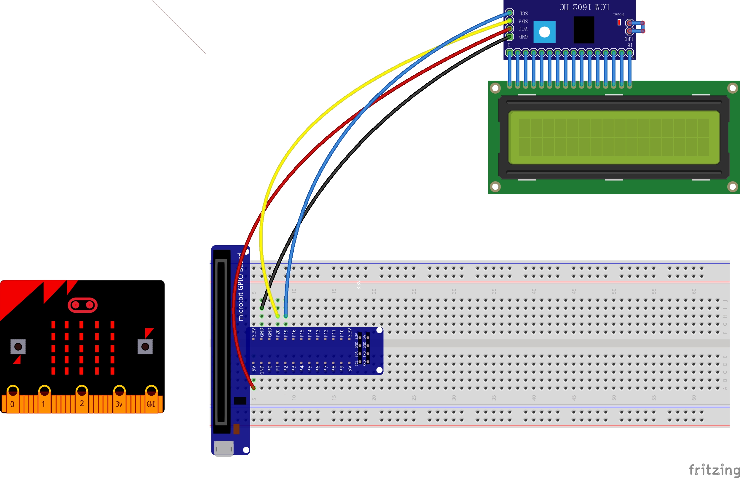
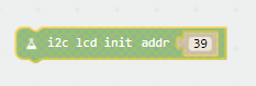
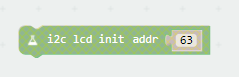
If the screen is not bright, please check the wires. If the screen is bright, but you do not see the above results, please check you I2C address.
The backlight is on and turns of and waits to turn back on but it never shows the text. Do you know why> I have the adeept IIC/I2C chip, the adeept 1602a display, and a version 1.5 microbit.


The backlight is on and turns of and waits to turn back on but it never shows the text. Do you know why> I have the adeept IIC/I2C chip, the adeept 1602a display, and a version 1.5 microbit.
I am also using the adeept jumper cables and expansion board.
please rotate the screw and adjust the brightness , see following picture:
