Welcome to the first lesson of OSOYOO Basic board smart car!
Objective
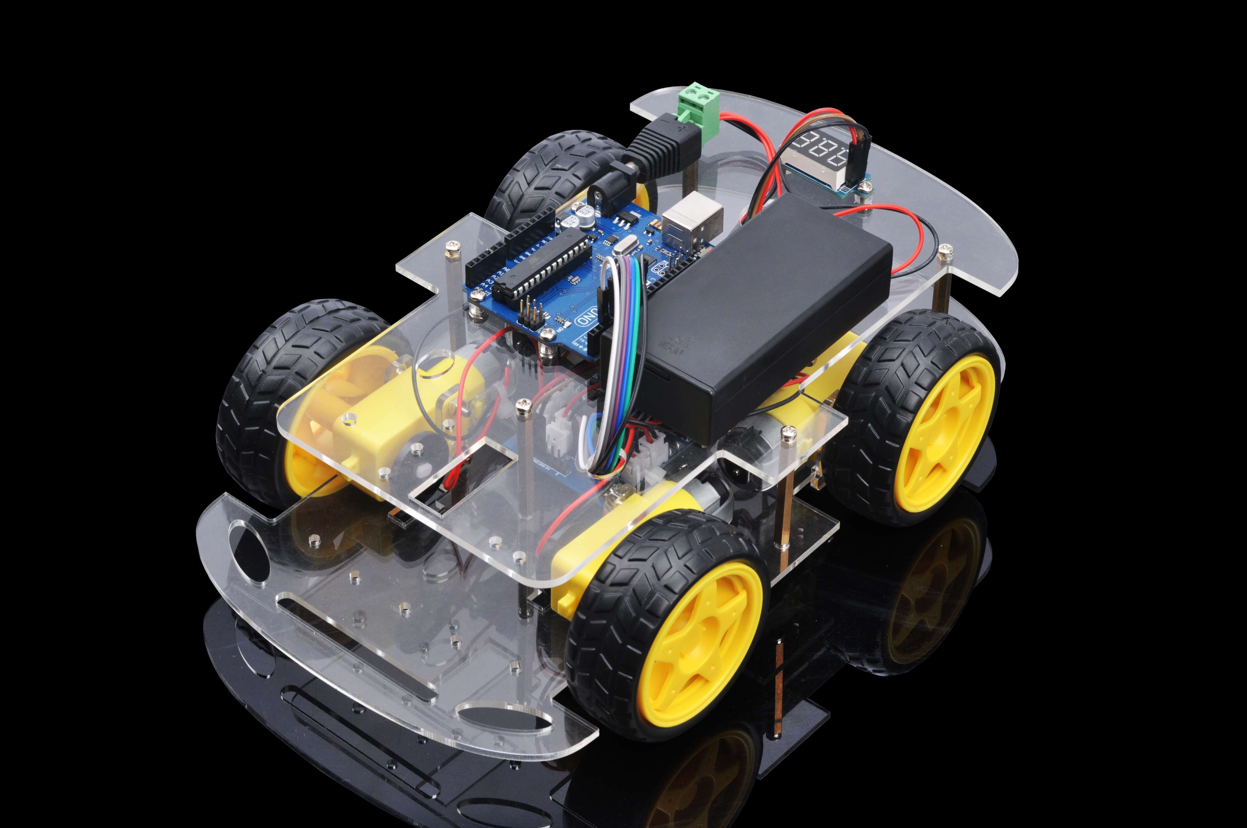
In this “Hello World” version lesson, we will install the most important framework in the smart car and program the car to do some simple movements. If you have passed the test movement of this lesson, it means Arduino, voltage meter,motor control module, motors, batteries,chassis and wire connections between these parts are all functioning well.
As your experiments in future lessons are all based on frame work of Lesson One, it is very important to test the installation and sample code in this Lesson properly.
Parts and Devices:
Device Name
picture
qty
Screw Number
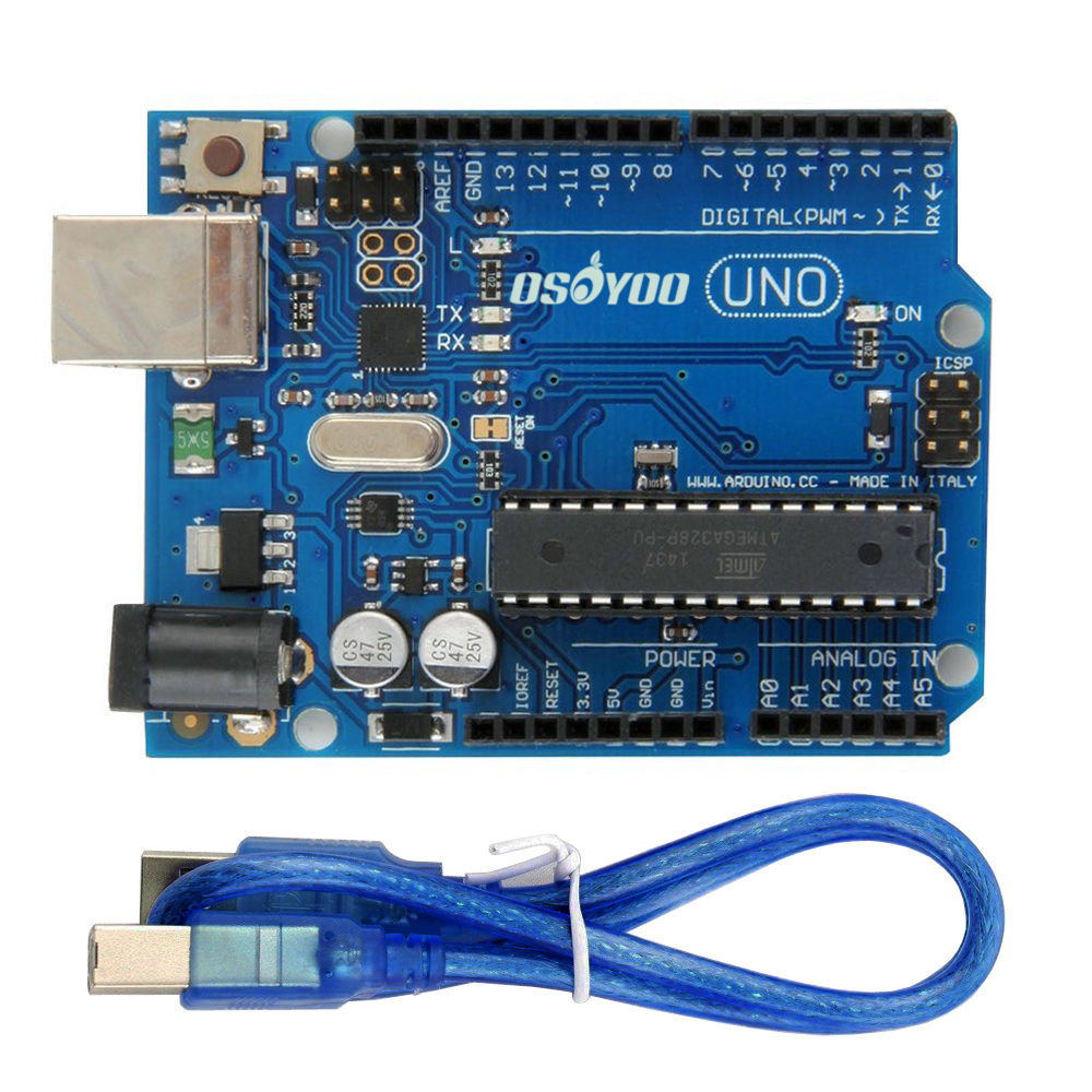
OSOYOO Basic board
1
M3 x 10 screws and nuts, washers
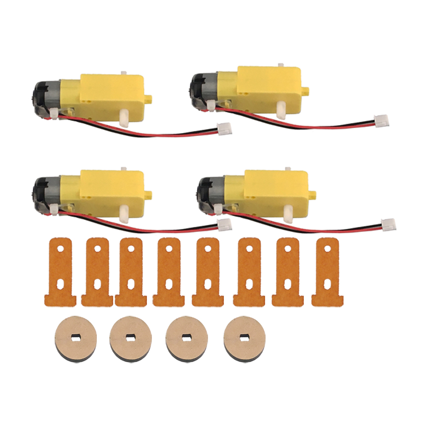
Motor with wires
4
M3 x 30 screws and nuts
Wheels
4
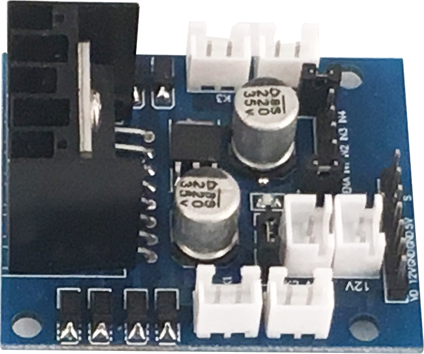
OSOYOO MODEL X MOTOR driver module
1
M3 x 10 screws and nuts, washers
Box for 18650 3.7V battery+
1
M3 x 10 screws and nuts
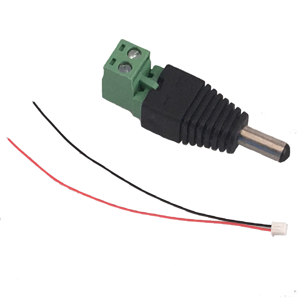
DC power connector
1
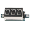
voltage meter
1
M3 x 10 screws and nuts, washers
Jumper wires(male-male,male-female)
some
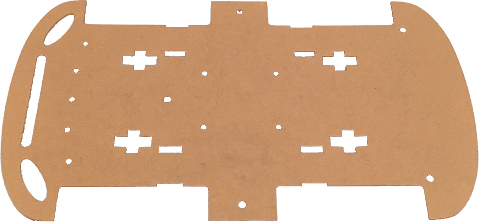
lower chassis
1
Copper pillar
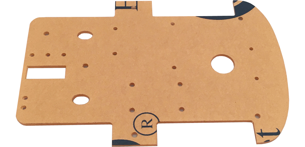
upper chassis
1
Copper pillar
Installation
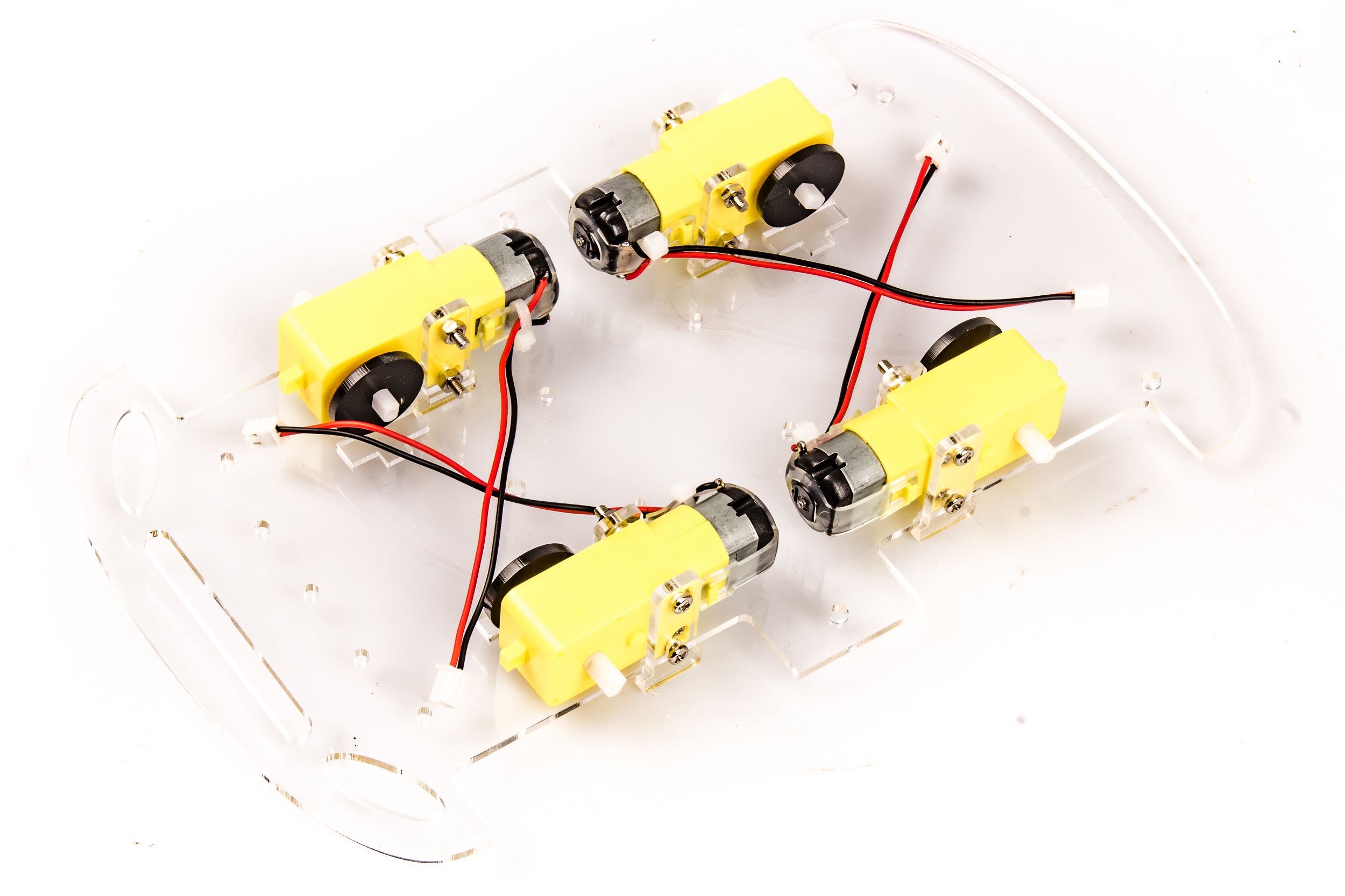
1)Connect 4 motors on lower chassis with screw M3 x 30
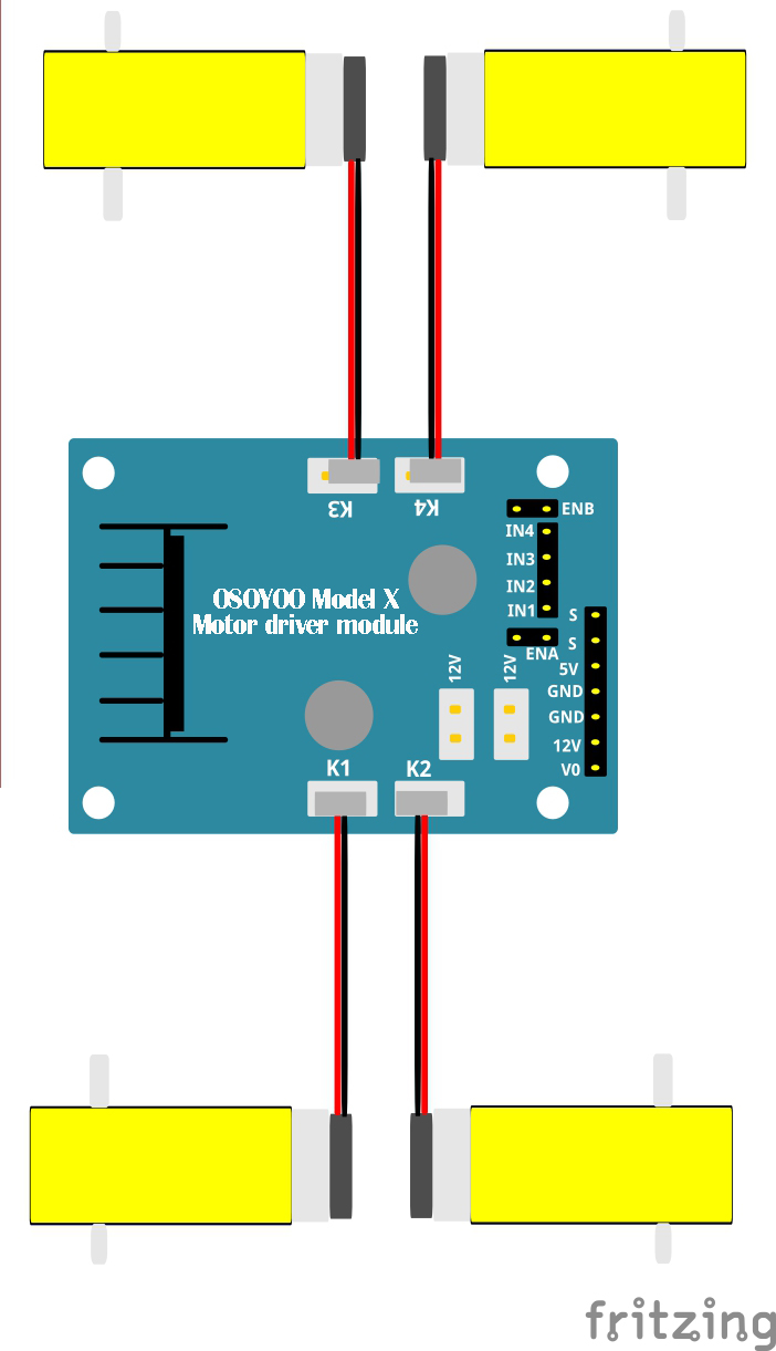
2)Install OSOYOO MODEL X motor driver module to lower chassis with screw M3 x 10, connect OSOYOO MODEL X motor driver module K1 to K4 sockets to 4 motors as per following graph:
3)Install OSOYOO Basic board on upper chassis with screw M3 x 10
4)Install Battery Box on upper chassis with screw M3 x 10
5)Install Voltage meter on upper chassis with screw M3 x 10
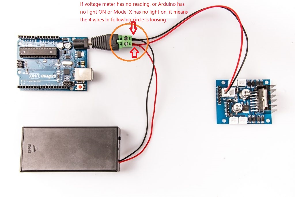
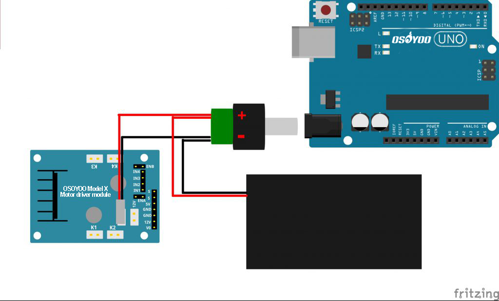
6) Connect the Uno board, battery box, Voltage Meter and OSOYOO MODEL X motor dirver module according below connection diagram:
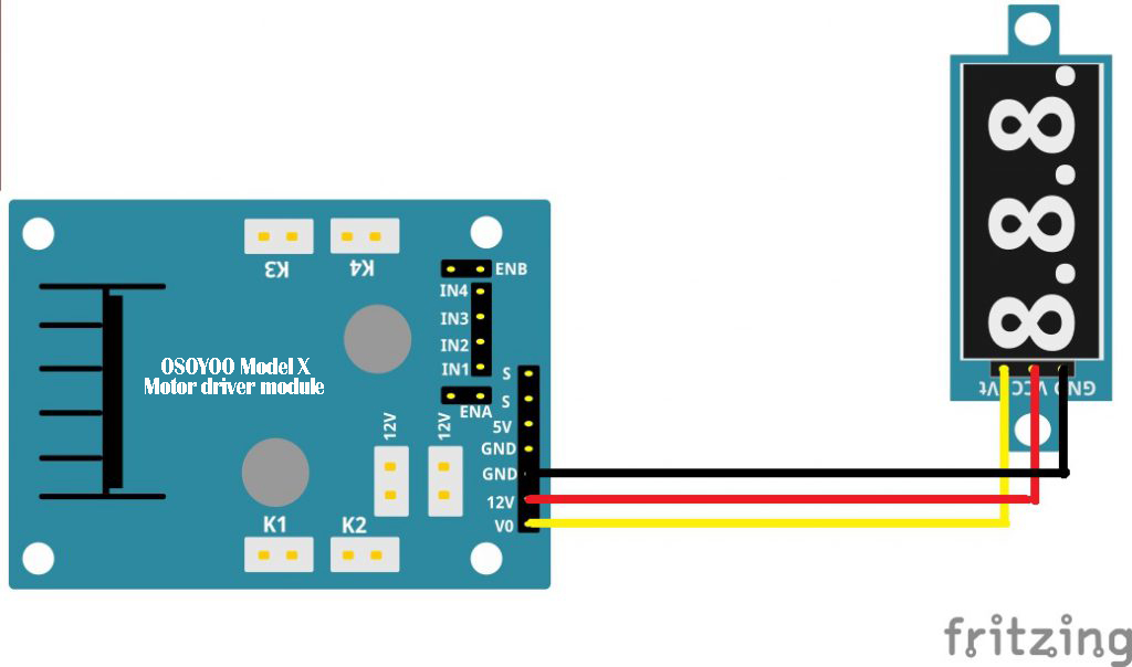
7)Connect Voltage Meter to OSOYOO MODEL X motor dirver module as below connection diagram.
Voltage Meter
OSOYOO MODEL X motor dirver module
GND
GND
VCC
12V
Vt
V0
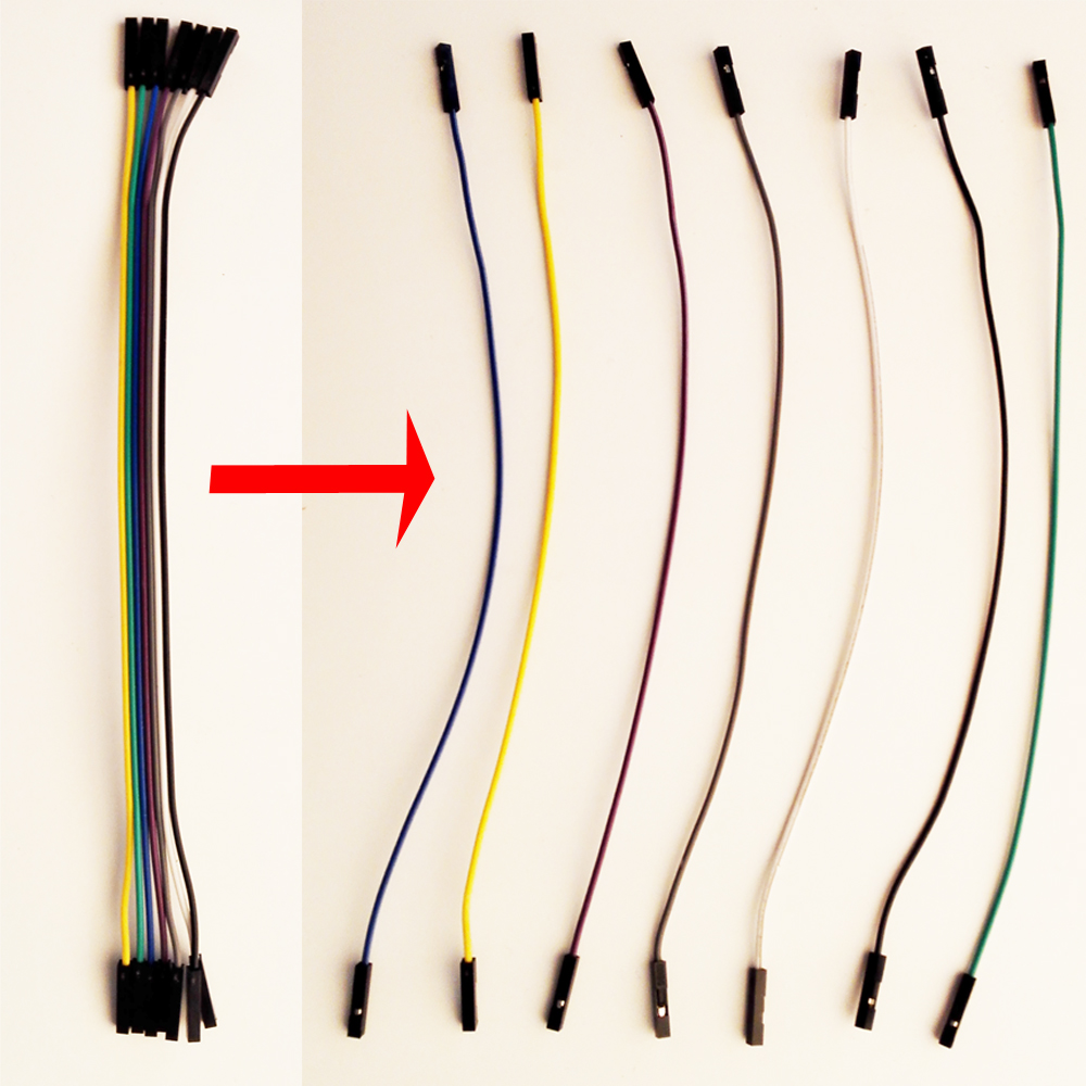
Please note: the bundle of female-female(male-female)jumper wires can be separated one by one:
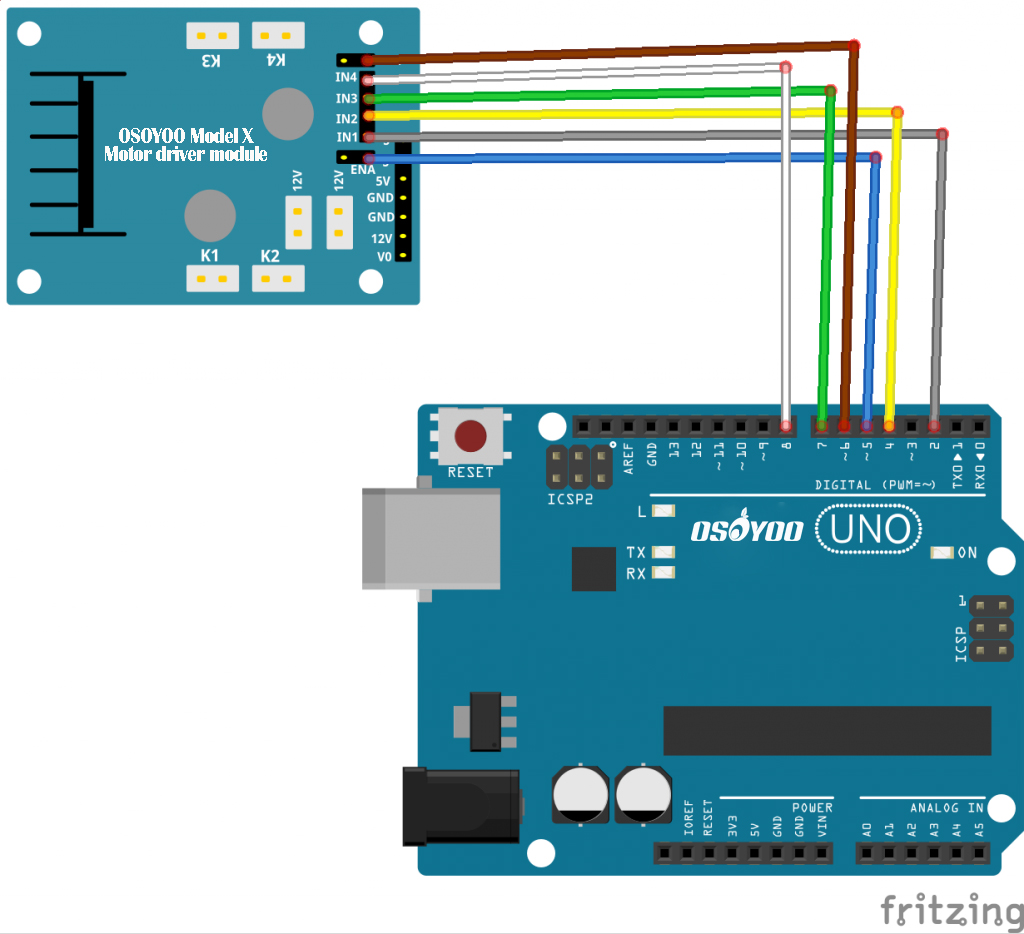
8)Connect OSOYOO Basic board D2,D4,D5,D6,D7,D8 to OSOYOO MODEL X motor driver module 6 control pins as per following graph
Uno R3 Board
OSOYOO MODEL X motor driver module
D2
IN1
D4
IN2
D5
ENA
D6
ENB
D7
IN3
D8
IN4
9)Connect upper chassis to lower chassis with five copper pillar screw supporters, then install 4 wheels onto the motors.
Now hardware installation is almost down. Before we install 18650 batteries into the box, we need burn the sample code into OSOYOO Basic board First.
Software Installation:
Step 1: Install latest Arduino IDE (If you have Arduino IDE version after 1.1.16, please skip this step)Download Arduino IDe from https://www.arduino.cc/en/Main/Software?setlang=en , then install the software.
Step 2: Download Lesson One sample code from https://osoyoo.com/driver/smartcar-lesson1.zip , unzip the download zip file smartcar-lesson1.zip, you will see a folder called smartcar-lesson1 .
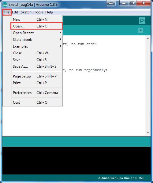
Step 3: Connect OSOYOO Basic board to PC with USB cable, Open Arduino IDE -> click file -> click Open -> choose code “smartcar-lesson1.ino” in smartcar-lesson1 folder, load the code into OSOYOO Basic board.
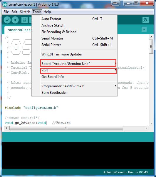
Step 4: Choose corresponding board/port for your project,upload the sketch to the board.
Final Testing :
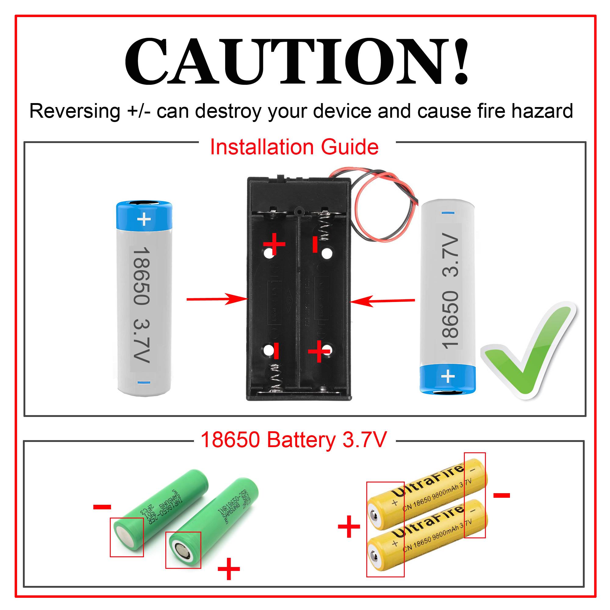
Note: the 18650 batterys we used in lessons are around 65 mm (2.56 inch) long, without an internal protection circuit.
Disconnect OSOYOO Basic board from PC, put 2 fully-charged 18650 battery into battery pox(check the box instruction and make sure polar direction is correct, otherwise it can destroy your device and cause fire hazard). Please intall your battery as per following instruction:
When you put the car on the ground, it should go forward 5 seconds, then go backward 5 seconds, then left turn for 5 seconds, then right turn for 5 seconds, then stop.
If the car does not move as per above mentioned result, you should check your wire connection, battery voltage(must over 7.2v).
Will someone please help me troubleshoot my robot? I have everything assembled and downloaded the smartcar-lesson1 code. When I turn on my robot my volt meter reads 8.2 and the wheels spin for maybe 0.1 seconds. After that, everything shuts down. I have checked the cables and they all seem to be in the correct spots. I have also checked to make sure all the white plug-in pieces are pushed in all the way.
Hello. I need some technical support. I built the robot, and installed the software. When I try to upload “smartcar-lesson1”, I get an error message that reads:
configuration.h: No such file or directory
exit status 1
configuration.h: No such file or directory
I cannot find any support for this anywhere. Does anyone have any ideas? Thank you.
your Arduino IDE software can not find the configuration.h file. it seems that you copy pasted the code of lesson 1 into Arduino IDE to compile it. This will not work. Correct procedures are as following:
Step 1: download the zip file from https://osoyoo.com/driver/smartcar-lesson1.zip
Step 2: unzip smartcar-lesson1.zip file downloaded from above link, you will see a folder named smartcar-lesson1
Step 3: enter the folder smartcar-lesson1, you will see two files: smartcar-lesson1.ino and configuration.h
Step 4: double click smartcar-lesson1.ino file , your Arduino IDE will automatically load smartcar-lesson1.ino and configuration.h into the programming window.
Step 5: click upload button or CTRL-U, compile the code. It should work.
If you have any question, please post comments here.
Thank you. That seemed to have worked from the messages on thebpc. However, when i put the charged batteries in, nothing happens at all. No lights, no movement, nothing. Any ideas?
The M3*10 screws I received are not long enough to go through the Motor Driver Module, washers, and chassis. The screws are not even long enough to go through without any washers. What is the fix for this?
i made the car, ran the sample code, and when i put it on the ground and tried to let the RC car run without the cord, it only runs with the cord but it does not run 5 seconds forwards backwards left or right.The voltage meter reads around 6 volts when its running and i checked my connections twice and im sure its okay. Any advice on how i should take care of this matter?
your battery create too much current and make the arduino shut down automatically. I changed the code in lesson 1 with less speed. please download new code from following link : https://osoyoo.com/download/code/smartcar-lesson1.zip
Hi, I just bought this device followed the steps. Code upload was successfully done. But after inserting the battery and turning it on It doesn’t do anything. I have attached an image please follow the link.
After turning the power on. Led lights marked with the green circle was supposed to turn on as it’s shown on the demo video(https://www.youtube.com/watch?v=9ETsbyjzD98) but in my case, it didn’t. Would appreciate if you could help with it.
For some reason, my voltmeter isn’t working. Do the batteries have to be fully charged in order to work? I am not sure if it is the batteries that are the issue, the connection of wires to the DC power connector, or the dc power connector itself?
My car is able to do single action like forward, backward, turn_left, and turn_right. However, if I change 4 pins in one time, my car will turn off itself. For example, it cannot change from go_advance to go_backward, or vice versa. Similarly, it cannot change from turn_left to turn_right, or vice versa. Do not know how to solve this.
Sorry. I am not quite understand what is your meaning for “change 4 pins in one time”. If you have assembled the car as per guide in lesson 1 and run the code, the car will make 4 movements in sequence: move forward ->move backward -> turn left -> turn right. Do you mean your car can not make above mentioned 4 movements?
Right. My car cannot move in the sequence as: move forward ->move backward -> turn left -> turn right. But it can move as: move forward -> turn left -> move backward -> turn right. The status of 4 pins for move forward is HIGH/LOW/HIGH/LOW, and move backward is LOW/HIGH/LOW/HIGH. Thus from forward to backward, 4 pins have changed, and my car shut down every time when 4 pin changed.
It is very likely that your battery is low. I suggest you purchase 18650 battery instead of 9V battery. 18650 battery has much higher capacity than 9V square battery and is rechargeable. The purchase link ishttps://www.amazon.com/OSOYOO-Battery-Charger-Rechargeable-Lithium/dp/B07ZR8NKJL/ref=sr_1_3?keywords=osoyoo+2+bay+18650+battery+USB+charger&qid=1577729504&sr=8-3
If you purchased any Osoyoo Robot car, you can send your order number to us and we can send you a 25% off coupon to buy this 18650 battery and charger package
I received the Robot Car Starter Kit as a gift. I completed set 1. I have 8+ volts to the meter, all power indications work correctly. The software uploaded correctly. When I turn on the power, the car starts to run the program – but as soon as the power goes to the driver motors, the circuit breaker flips and the whole system shuts down. I can reset the circuit breaker and repeat the problem. If I remove one of the driver motors (it doesn’t matter which one, I tried it with several), it works just fine…well, except for the issue that I only have three motors running. It seems something is drawing too much current. Without appropriate schematics, I am unable to troubleshoot. What help is available? [email protected]
More info: If I remove just one motor from the circuit – it runs forward, but trips the circuit when it tries to change direction. If 2 motors are removed from the circuit – it will run through the whole program.
Dropping the speed lessened the power draw and fixed the issue. Thank you for the updated code. Now I know to watch for the power draw when running all four motors.
I have a Model-X for my child.
I tried to make Model-X with lesson-1 web page.
But it didn’t work.
I checked the Arduino board (using LED brinking sketch) and the motors by direct connection to batteries.
They are OK, but the Model-X were NOT.
Finally I found the cause of fault.
The jumper wires (Male/Female (socket-plug) wires) are ALMOST broken (NOT connected).
15 wires (total 20 wires) are broken. They were NOT made properly.
IF your Model-X doesn’t work well, PLEASE check cables !!
it seems that your Arduino is not connected to COM5. You need go to Arduino IDE ->Tool ->Port and select correct COMM port which is connected to your Arduino UNO board.
Hi friend,
Do you solve this issue?
I’m sorry that there are something wrong with our website before, and I can’t see your comment.
If any query, please feel free to contact with my email address: [email protected].
Elaine
Hi friend,
Do you solve this issue?
I’m sorry that there are something wrong with our website before, and I can’t see your comment.
If any query, please feel free to contact with my email address: [email protected].
Elaine
which battery to buy
I bought 18650 3.7v battery, 2000mAH
it doesn’t fit the battery box
also when I adjusted the spring in the battery box
within moments it started to burn
Hi friend,
Do you solve this issue?
I’m sorry that there are something wrong with our website before, and I can’t see your comment.
If any query, please feel free to contact with my email address: [email protected].
Elaine
if you car moving direction is not as expectation, normally it is because the motor driver board(model X) Pins IN1,IN2,IN3,IN4 connecting to D2,D4,D7,D8 are not correct. I suggest you switch the pins on D2,D4 and then switch pins on D7 and D8. Then your car should go correct direction.
My car moved when I first uploaded first lesson, but then i uploaded other codes and now car is not moving. I tried to start from scratch, and still all light are on but no movement even after i uploaded the code one more time, also i see that have so many libraries, do i need to reset my Arduino?
your arduino version might have some conflict with old lesson 1 code. Please remove the smartcar-lesson1 folder from your computer, then download new code from https://osoyoo.com/driver/smartcar-lesson1a.zip ,unzip and try the new code again.
(I posted the following reply to another thread by mistake)
I ordered this item from amazon.de as you suggested, as a Christmas present.
I was promised a delivery date for today (dec 30) and got a tracking code from amazon.de for an operator called iparcel-eu.
Their website (https://www.i-parcel.com/) gives the impression that it is a UPS outfit, and all their contact links point to UPS profiles.
However, it’s already late in the day and not a peep. I called UPS on the phone and they claim this is a totally different company and they cannot help me with locating my parcel. All they could do was forward my email somewhere they wouldn’t say.
Moreover, the iparcel site has no contact details to check whether delivery will take place.
Subsequently I came across some very bad reviews of that courier service (https://ie.trustpilot.com/review/i-parcel.com). I hope I don’t regret my decision to buy this item as a Christmas present. However, knowing what I know now, I would look to shop elsewhere. Crossing my fingers they deliver in the few working hours that remain…
I am so sorry to know that Amazon Germany delayed your shipment. Can you give us your order no. and we might contact Amazon directly to figure out what is the shipping problem? Normally Amazon delivery in North America is very fast and reliable. I believe their Europe logistic network is very new and not able to handle so many orders in this Xmas season. Sorry again for any inconvenience caused.
I successfully completed lesson 1, installed the IR receiver for lesson 2, but the remote seems dead.
I changed battery and nothing. I tested its lamp with my smartphone camera and I see no light.
The IR receiver “understands” the TV remote, as the red light lights up when I target it and press a button (I also see its lamp with my smartphone camera).
Ok. If your remote is defective, we can send you a new remote. please email your order no. and address to [email protected]. We will mail you a new IR remote once we get your email.
In waiting for the delivery, I am trying to make this play with my Samsung TV remote.
I found some raw hex codes for the Samsung remote’s buttons at http://www.remotecentral.com/cgi-bin/codes/samsung/tv_functions/ but I am having trouble translating them to the hex format understood by the UNO board (I suppose it must be similar to the code in the code of lesson 2).
OK, from the serial port I found the changes I need to make to the code:
//Samsung remote. From serial monitor as per instructions on https://www.youtube.com/watch?v=IVToijhx0ck
#define IR_ADVANCE 0xC26BF044 //codefromIRcontroller”▲”button
#define IR_BACK 0xE0E08679 //codefromIRcontroller”▼”button
#define IR_RIGHT 0x53801EE8 //codefromIRcontroller”>”button
#define IR_LEFT 0x758C9D82 //codefromIRcontroller”<"button
#define IR_STOP 0xE0E016E9 //codefromIRcontroller"Enter"button
#define IR_turnsmallleft 0x3BCD58C8 //codefromIRcontroller"Return"button
I’m a little stuck because I don’t have enough M3 nuts to secure the Arduino, motor board thing, and the battery holder. It only came with 5 M3 nuts and 14 M3 screws. Am I missing something?!
I have followed the instructions in the kit. I have put a 9V battery. The red engine led and the green UNO led come on, and an orange light flashes, but the car does not move. What have I done wrong?
We don’t have much detail about your problem. Do you have any compiling errors? if yes, what is the error?
if no compiling error, then it should be connection problem.
Please connect following pins of Model X board:
ENA to Arduino 5V
IN1 to Arduino 5V
IN2 to Arduino GND
Right motor to K1 port
If right motor rotates, then it means your ENA ,IN1,IN2 wires are ok. Otherwise one of these wires are broken.
Then connect
ENB to Arduino 5V
IN3 to Arduino 5V
IN4 to Arduino GND
Left motor to K3 port
If left motor rotates, then it means your ENB ,IN3,IN4 wires are ok. Otherwise there might broken wires in these 3 wires. you need change wires.
I built the car, uploaded the first example code, it was acting very very strangely. I audited the code. Tried a bunch of minimal examples. Nothing made sense. I took the car apart and found that I received the wrong motors.
I have three black-red motors and one red-black motor.
Anyway you can send me the missing red-black motor or can I purchase it somewhere?


How do I know if my voltage meter is working?
I connected everything correctly but it the voltage meter isn’t functioning.
What may I be doing wrong?
Are you willing to take a photo about the voltage meter and battery and send to my email address: [email protected]?
Hi
I followed step by step but MODEL X motor driver not work; What I will be do ???
my email: [email protected]
Will someone please help me troubleshoot my robot? I have everything assembled and downloaded the smartcar-lesson1 code. When I turn on my robot my volt meter reads 8.2 and the wheels spin for maybe 0.1 seconds. After that, everything shuts down. I have checked the cables and they all seem to be in the correct spots. I have also checked to make sure all the white plug-in pieces are pushed in all the way.
what is the voltage meter reading Make sure your voltage is over 8.0 Volt
what is the voltage meter reading? Make sure your voltage is over 8.0 Volt.
Hello. I need some technical support. I built the robot, and installed the software. When I try to upload “smartcar-lesson1”, I get an error message that reads:
configuration.h: No such file or directory
exit status 1
configuration.h: No such file or directory
I cannot find any support for this anywhere. Does anyone have any ideas? Thank you.
your Arduino IDE software can not find the configuration.h file. it seems that you copy pasted the code of lesson 1 into Arduino IDE to compile it. This will not work. Correct procedures are as following:
Step 1: download the zip file from https://osoyoo.com/driver/smartcar-lesson1.zip
Step 2: unzip smartcar-lesson1.zip file downloaded from above link, you will see a folder named smartcar-lesson1
Step 3: enter the folder smartcar-lesson1, you will see two files: smartcar-lesson1.ino and configuration.h
Step 4: double click smartcar-lesson1.ino file , your Arduino IDE will automatically load smartcar-lesson1.ino and configuration.h into the programming window.
Step 5: click upload button or CTRL-U, compile the code. It should work.
If you have any question, please post comments here.
Thank you. That seemed to have worked from the messages on thebpc. However, when i put the charged batteries in, nothing happens at all. No lights, no movement, nothing. Any ideas?
Sorry. Ignore that last post. I was able to figure out the issue.
The M3*10 screws I received are not long enough to go through the Motor Driver Module, washers, and chassis. The screws are not even long enough to go through without any washers. What is the fix for this?
i made the car, ran the sample code, and when i put it on the ground and tried to let the RC car run without the cord, it only runs with the cord but it does not run 5 seconds forwards backwards left or right.The voltage meter reads around 6 volts when its running and i checked my connections twice and im sure its okay. Any advice on how i should take care of this matter?
your battery create too much current and make the arduino shut down automatically. I changed the code in lesson 1 with less speed. please download new code from following link : https://osoyoo.com/download/code/smartcar-lesson1.zip
Let me know if it works.
admin
Wrong thread, please see the comment at its correct thread below.
Hi, I just bought this device followed the steps. Code upload was successfully done. But after inserting the battery and turning it on It doesn’t do anything. I have attached an image please follow the link.
https://drive.google.com/open?id=1iHEfYE4y6VV-vuYRsfnf14Fl5VOeLG37
After turning the power on. Led lights marked with the green circle was supposed to turn on as it’s shown on the demo video(https://www.youtube.com/watch?v=9ETsbyjzD98) but in my case, it didn’t. Would appreciate if you could help with it.
FYI: I use Mac.
It seems that your car has no power from battery. Normally the reason is that you did not connect 4 wires in the battery DC connector properly (check the red circle in this picture https://osoyoo.com/wp-content/uploads/2017/04/2-1-1024×682.jpg ) .
Please reconnect the DC connector wires and try again. If you have any question, email to [email protected] .
Hi,
My bad. There was a wiring problem. It works fine now. 🙂
Hi ,
For 3.7 volt battery 18650 , how many mah (milli-Ampere hour) this battery should have ?
can i use the 2200 mah battery ?
For some reason, my voltmeter isn’t working. Do the batteries have to be fully charged in order to work? I am not sure if it is the batteries that are the issue, the connection of wires to the DC power connector, or the dc power connector itself?
My car is able to do single action like forward, backward, turn_left, and turn_right. However, if I change 4 pins in one time, my car will turn off itself. For example, it cannot change from go_advance to go_backward, or vice versa. Similarly, it cannot change from turn_left to turn_right, or vice versa. Do not know how to solve this.
Sorry. I am not quite understand what is your meaning for “change 4 pins in one time”. If you have assembled the car as per guide in lesson 1 and run the code, the car will make 4 movements in sequence: move forward ->move backward -> turn left -> turn right. Do you mean your car can not make above mentioned 4 movements?
Right. My car cannot move in the sequence as: move forward ->move backward -> turn left -> turn right. But it can move as: move forward -> turn left -> move backward -> turn right. The status of 4 pins for move forward is HIGH/LOW/HIGH/LOW, and move backward is LOW/HIGH/LOW/HIGH. Thus from forward to backward, 4 pins have changed, and my car shut down every time when 4 pin changed.
It is very likely that your battery is low. I suggest you purchase 18650 battery instead of 9V battery. 18650 battery has much higher capacity than 9V square battery and is rechargeable. The purchase link ishttps://www.amazon.com/OSOYOO-Battery-Charger-Rechargeable-Lithium/dp/B07ZR8NKJL/ref=sr_1_3?keywords=osoyoo+2+bay+18650+battery+USB+charger&qid=1577729504&sr=8-3
If you purchased any Osoyoo Robot car, you can send your order number to us and we can send you a 25% off coupon to buy this 18650 battery and charger package
I received the Robot Car Starter Kit as a gift. I completed set 1. I have 8+ volts to the meter, all power indications work correctly. The software uploaded correctly. When I turn on the power, the car starts to run the program – but as soon as the power goes to the driver motors, the circuit breaker flips and the whole system shuts down. I can reset the circuit breaker and repeat the problem. If I remove one of the driver motors (it doesn’t matter which one, I tried it with several), it works just fine…well, except for the issue that I only have three motors running. It seems something is drawing too much current. Without appropriate schematics, I am unable to troubleshoot. What help is available? [email protected]
More info: If I remove just one motor from the circuit – it runs forward, but trips the circuit when it tries to change direction. If 2 motors are removed from the circuit – it will run through the whole program.
We changed the code for lesson 1 , please download new code from following link : https://osoyoo.com/download/code/smartcar-lesson1.zip
Let me know if this code works.
Happy New Year!
admin
Dropping the speed lessened the power draw and fixed the issue. Thank you for the updated code. Now I know to watch for the power draw when running all four motors.
I have a Model-X for my child.
I tried to make Model-X with lesson-1 web page.
But it didn’t work.
I checked the Arduino board (using LED brinking sketch) and the motors by direct connection to batteries.
They are OK, but the Model-X were NOT.
Finally I found the cause of fault.
The jumper wires (Male/Female (socket-plug) wires) are ALMOST broken (NOT connected).
15 wires (total 20 wires) are broken. They were NOT made properly.
IF your Model-X doesn’t work well, PLEASE check cables !!
getting error while uploading the software.
Arduino: 1.8.8 (Windows Store 1.8.19.0) (Windows 10), Board: “Arduino/Genuino Uno”
C:\Program Files\WindowsApps\ArduinoLLC.ArduinoIDE_1.8.19.0_x86__mdqgnx93n4wtt\arduino-builder -dump-prefs -logger=machine -hardware C:\Program Files\WindowsApps\ArduinoLLC.ArduinoIDE_1.8.19.0_x86__mdqgnx93n4wtt\hardware -tools C:\Program Files\WindowsApps\ArduinoLLC.ArduinoIDE_1.8.19.0_x86__mdqgnx93n4wtt\tools-builder -tools C:\Program Files\WindowsApps\ArduinoLLC.ArduinoIDE_1.8.19.0_x86__mdqgnx93n4wtt\hardware\tools\avr -built-in-libraries C:\Program Files\WindowsApps\ArduinoLLC.ArduinoIDE_1.8.19.0_x86__mdqgnx93n4wtt\libraries -libraries C:\Users\sreej\OneDrive\Documents\Arduino\libraries -fqbn=arduino:avr:uno -ide-version=10808 -build-path C:\Users\sreej\AppData\Local\Temp\arduino_build_204344 -warnings=none -build-cache C:\Users\sreej\AppData\Local\Temp\arduino_cache_291323 -prefs=build.warn_data_percentage=75 -prefs=runtime.tools.avr-gcc.path=C:\Program Files\WindowsApps\ArduinoLLC.ArduinoIDE_1.8.19.0_x86__mdqgnx93n4wtt\hardware\tools\avr -prefs=runtime.tools.avr-gcc-5.4.0-atmel3.6.1-arduino2.path=C:\Program Files\WindowsApps\ArduinoLLC.ArduinoIDE_1.8.19.0_x86__mdqgnx93n4wtt\hardware\tools\avr -prefs=runtime.tools.avrdude.path=C:\Program Files\WindowsApps\ArduinoLLC.ArduinoIDE_1.8.19.0_x86__mdqgnx93n4wtt\hardware\tools\avr -prefs=runtime.tools.avrdude-6.3.0-arduino14.path=C:\Program Files\WindowsApps\ArduinoLLC.ArduinoIDE_1.8.19.0_x86__mdqgnx93n4wtt\hardware\tools\avr -prefs=runtime.tools.arduinoOTA.path=C:\Program Files\WindowsApps\ArduinoLLC.ArduinoIDE_1.8.19.0_x86__mdqgnx93n4wtt\hardware\tools\avr -prefs=runtime.tools.arduinoOTA-1.2.1.path=C:\Program Files\WindowsApps\ArduinoLLC.ArduinoIDE_1.8.19.0_x86__mdqgnx93n4wtt\hardware\tools\avr -verbose C:\Thara\smartcar-lesson1\smartcar-lesson1\smartcar-lesson1.ino
C:\Program Files\WindowsApps\ArduinoLLC.ArduinoIDE_1.8.19.0_x86__mdqgnx93n4wtt\arduino-builder -compile -logger=machine -hardware C:\Program Files\WindowsApps\ArduinoLLC.ArduinoIDE_1.8.19.0_x86__mdqgnx93n4wtt\hardware -tools C:\Program Files\WindowsApps\ArduinoLLC.ArduinoIDE_1.8.19.0_x86__mdqgnx93n4wtt\tools-builder -tools C:\Program Files\WindowsApps\ArduinoLLC.ArduinoIDE_1.8.19.0_x86__mdqgnx93n4wtt\hardware\tools\avr -built-in-libraries C:\Program Files\WindowsApps\ArduinoLLC.ArduinoIDE_1.8.19.0_x86__mdqgnx93n4wtt\libraries -libraries C:\Users\sreej\OneDrive\Documents\Arduino\libraries -fqbn=arduino:avr:uno -ide-version=10808 -build-path C:\Users\sreej\AppData\Local\Temp\arduino_build_204344 -warnings=none -build-cache C:\Users\sreej\AppData\Local\Temp\arduino_cache_291323 -prefs=build.warn_data_percentage=75 -prefs=runtime.tools.avr-gcc.path=C:\Program Files\WindowsApps\ArduinoLLC.ArduinoIDE_1.8.19.0_x86__mdqgnx93n4wtt\hardware\tools\avr -prefs=runtime.tools.avr-gcc-5.4.0-atmel3.6.1-arduino2.path=C:\Program Files\WindowsApps\ArduinoLLC.ArduinoIDE_1.8.19.0_x86__mdqgnx93n4wtt\hardware\tools\avr -prefs=runtime.tools.avrdude.path=C:\Program Files\WindowsApps\ArduinoLLC.ArduinoIDE_1.8.19.0_x86__mdqgnx93n4wtt\hardware\tools\avr -prefs=runtime.tools.avrdude-6.3.0-arduino14.path=C:\Program Files\WindowsApps\ArduinoLLC.ArduinoIDE_1.8.19.0_x86__mdqgnx93n4wtt\hardware\tools\avr -prefs=runtime.tools.arduinoOTA.path=C:\Program Files\WindowsApps\ArduinoLLC.ArduinoIDE_1.8.19.0_x86__mdqgnx93n4wtt\hardware\tools\avr -prefs=runtime.tools.arduinoOTA-1.2.1.path=C:\Program Files\WindowsApps\ArduinoLLC.ArduinoIDE_1.8.19.0_x86__mdqgnx93n4wtt\hardware\tools\avr -verbose C:\Thara\smartcar-lesson1\smartcar-lesson1\smartcar-lesson1.ino
Using board ‘uno’ from platform in folder: C:\Program Files\WindowsApps\ArduinoLLC.ArduinoIDE_1.8.19.0_x86__mdqgnx93n4wtt\hardware\arduino\avr
Using core ‘arduino’ from platform in folder: C:\Program Files\WindowsApps\ArduinoLLC.ArduinoIDE_1.8.19.0_x86__mdqgnx93n4wtt\hardware\arduino\avr
Detecting libraries used…
“C:\\Program Files\\WindowsApps\\ArduinoLLC.ArduinoIDE_1.8.19.0_x86__mdqgnx93n4wtt\\hardware\\tools\\avr/bin/avr-g++” -c -g -Os -w -std=gnu++11 -fpermissive -fno-exceptions -ffunction-sections -fdata-sections -fno-threadsafe-statics -Wno-error=narrowing -flto -w -x c++ -E -CC -mmcu=atmega328p -DF_CPU=16000000L -DARDUINO=10808 -DARDUINO_AVR_UNO -DARDUINO_ARCH_AVR “-IC:\\Program Files\\WindowsApps\\ArduinoLLC.ArduinoIDE_1.8.19.0_x86__mdqgnx93n4wtt\\hardware\\arduino\\avr\\cores\\arduino” “-IC:\\Program Files\\WindowsApps\\ArduinoLLC.ArduinoIDE_1.8.19.0_x86__mdqgnx93n4wtt\\hardware\\arduino\\avr\\variants\\standard” “C:\\Users\\sreej\\AppData\\Local\\Temp\\arduino_build_204344\\sketch\\smartcar-lesson1.ino.cpp” -o nul
Generating function prototypes…
“C:\\Program Files\\WindowsApps\\ArduinoLLC.ArduinoIDE_1.8.19.0_x86__mdqgnx93n4wtt\\hardware\\tools\\avr/bin/avr-g++” -c -g -Os -w -std=gnu++11 -fpermissive -fno-exceptions -ffunction-sections -fdata-sections -fno-threadsafe-statics -Wno-error=narrowing -flto -w -x c++ -E -CC -mmcu=atmega328p -DF_CPU=16000000L -DARDUINO=10808 -DARDUINO_AVR_UNO -DARDUINO_ARCH_AVR “-IC:\\Program Files\\WindowsApps\\ArduinoLLC.ArduinoIDE_1.8.19.0_x86__mdqgnx93n4wtt\\hardware\\arduino\\avr\\cores\\arduino” “-IC:\\Program Files\\WindowsApps\\ArduinoLLC.ArduinoIDE_1.8.19.0_x86__mdqgnx93n4wtt\\hardware\\arduino\\avr\\variants\\standard” “C:\\Users\\sreej\\AppData\\Local\\Temp\\arduino_build_204344\\sketch\\smartcar-lesson1.ino.cpp” -o “C:\\Users\\sreej\\AppData\\Local\\Temp\\arduino_build_204344\\preproc\\ctags_target_for_gcc_minus_e.cpp”
“C:\\Program Files\\WindowsApps\\ArduinoLLC.ArduinoIDE_1.8.19.0_x86__mdqgnx93n4wtt\\tools-builder\\ctags\\5.8-arduino11/ctags” -u –language-force=c++ -f – –c++-kinds=svpf –fields=KSTtzns –line-directives “C:\\Users\\sreej\\AppData\\Local\\Temp\\arduino_build_204344\\preproc\\ctags_target_for_gcc_minus_e.cpp”
Compiling sketch…
“C:\\Program Files\\WindowsApps\\ArduinoLLC.ArduinoIDE_1.8.19.0_x86__mdqgnx93n4wtt\\hardware\\tools\\avr/bin/avr-g++” -c -g -Os -w -std=gnu++11 -fpermissive -fno-exceptions -ffunction-sections -fdata-sections -fno-threadsafe-statics -Wno-error=narrowing -MMD -flto -mmcu=atmega328p -DF_CPU=16000000L -DARDUINO=10808 -DARDUINO_AVR_UNO -DARDUINO_ARCH_AVR “-IC:\\Program Files\\WindowsApps\\ArduinoLLC.ArduinoIDE_1.8.19.0_x86__mdqgnx93n4wtt\\hardware\\arduino\\avr\\cores\\arduino” “-IC:\\Program Files\\WindowsApps\\ArduinoLLC.ArduinoIDE_1.8.19.0_x86__mdqgnx93n4wtt\\hardware\\arduino\\avr\\variants\\standard” “C:\\Users\\sreej\\AppData\\Local\\Temp\\arduino_build_204344\\sketch\\smartcar-lesson1.ino.cpp” -o “C:\\Users\\sreej\\AppData\\Local\\Temp\\arduino_build_204344\\sketch\\smartcar-lesson1.ino.cpp.o”
Compiling libraries…
Compiling core…
Using precompiled core: C:\Users\sreej\AppData\Local\Temp\arduino_cache_291323\core\core_arduino_avr_uno_1465f6d64018740f7e766831526df7ff.a
Linking everything together…
“C:\\Program Files\\WindowsApps\\ArduinoLLC.ArduinoIDE_1.8.19.0_x86__mdqgnx93n4wtt\\hardware\\tools\\avr/bin/avr-gcc” -w -Os -g -flto -fuse-linker-plugin -Wl,–gc-sections -mmcu=atmega328p -o “C:\\Users\\sreej\\AppData\\Local\\Temp\\arduino_build_204344/smartcar-lesson1.ino.elf” “C:\\Users\\sreej\\AppData\\Local\\Temp\\arduino_build_204344\\sketch\\smartcar-lesson1.ino.cpp.o” “C:\\Users\\sreej\\AppData\\Local\\Temp\\arduino_build_204344/..\\arduino_cache_291323\\core\\core_arduino_avr_uno_1465f6d64018740f7e766831526df7ff.a” “-LC:\\Users\\sreej\\AppData\\Local\\Temp\\arduino_build_204344” -lm
“C:\\Program Files\\WindowsApps\\ArduinoLLC.ArduinoIDE_1.8.19.0_x86__mdqgnx93n4wtt\\hardware\\tools\\avr/bin/avr-objcopy” -O ihex -j .eeprom –set-section-flags=.eeprom=alloc,load –no-change-warnings –change-section-lma .eeprom=0 “C:\\Users\\sreej\\AppData\\Local\\Temp\\arduino_build_204344/smartcar-lesson1.ino.elf” “C:\\Users\\sreej\\AppData\\Local\\Temp\\arduino_build_204344/smartcar-lesson1.ino.eep”
“C:\\Program Files\\WindowsApps\\ArduinoLLC.ArduinoIDE_1.8.19.0_x86__mdqgnx93n4wtt\\hardware\\tools\\avr/bin/avr-objcopy” -O ihex -R .eeprom “C:\\Users\\sreej\\AppData\\Local\\Temp\\arduino_build_204344/smartcar-lesson1.ino.elf” “C:\\Users\\sreej\\AppData\\Local\\Temp\\arduino_build_204344/smartcar-lesson1.ino.hex”
“C:\\Program Files\\WindowsApps\\ArduinoLLC.ArduinoIDE_1.8.19.0_x86__mdqgnx93n4wtt\\hardware\\tools\\avr/bin/avr-size” -A “C:\\Users\\sreej\\AppData\\Local\\Temp\\arduino_build_204344/smartcar-lesson1.ino.elf”
Sketch uses 1190 bytes (3%) of program storage space. Maximum is 32256 bytes.
Global variables use 9 bytes (0%) of dynamic memory, leaving 2039 bytes for local variables. Maximum is 2048 bytes.
C:\Program Files\WindowsApps\ArduinoLLC.ArduinoIDE_1.8.19.0_x86__mdqgnx93n4wtt\hardware\tools\avr/bin/avrdude -CC:\Program Files\WindowsApps\ArduinoLLC.ArduinoIDE_1.8.19.0_x86__mdqgnx93n4wtt\hardware\tools\avr/etc/avrdude.conf -v -patmega328p -carduino -PCOM5 -b115200 -D -Uflash:w:C:\Users\sreej\AppData\Local\Temp\arduino_build_204344/smartcar-lesson1.ino.hex:i
avrdude: Version 6.3-20171130
Copyright (c) 2000-2005 Brian Dean, http://www.bdmicro.com/
Copyright (c) 2007-2014 Joerg Wunsch
System wide configuration file is “C:\Program Files\WindowsApps\ArduinoLLC.ArduinoIDE_1.8.19.0_x86__mdqgnx93n4wtt\hardware\tools\avr/etc/avrdude.conf”
Using Port : COM5
Using Programmer : arduino
Overriding Baud Rate : 115200
An error occurred while uploading the sketch
Please help.
it seems that your Arduino is not connected to COM5. You need go to Arduino IDE ->Tool ->Port and select correct COMM port which is connected to your Arduino UNO board.
i could only see COM6 and COM4
could you please respond to the issue we are facing
Hi friend,
Do you solve this issue?
I’m sorry that there are something wrong with our website before, and I can’t see your comment.
If any query, please feel free to contact with my email address: [email protected].
Elaine
Hi friend,
Do you solve this issue?
I’m sorry that there are something wrong with our website before, and I can’t see your comment.
If any query, please feel free to contact with my email address: [email protected].
Elaine
which battery to buy
I bought 18650 3.7v battery, 2000mAH
it doesn’t fit the battery box
also when I adjusted the spring in the battery box
within moments it started to burn
pl advice
Hi friend,
Do you solve this issue?
I’m sorry that there are something wrong with our website before, and I can’t see your comment.
If any query, please feel free to contact with my email address: [email protected].
Elaine
Why does the car go backwards when it moves forward?
if you car moving direction is not as expectation, normally it is because the motor driver board(model X) Pins IN1,IN2,IN3,IN4 connecting to D2,D4,D7,D8 are not correct. I suggest you switch the pins on D2,D4 and then switch pins on D7 and D8. Then your car should go correct direction.
My car moved when I first uploaded first lesson, but then i uploaded other codes and now car is not moving. I tried to start from scratch, and still all light are on but no movement even after i uploaded the code one more time, also i see that have so many libraries, do i need to reset my Arduino?
Arduino: 1.8.9 (Windows 10), Board: “Arduino/Genuino Uno”
smartcar-lesson1:15:27: error: configuration.h: No such file or directory
compilation terminated.
exit status 1
configuration.h: No such file or directory
This report would have more information with
“Show verbose output during compilation”
option enabled in File -> Preferences.
your arduino version might have some conflict with old lesson 1 code. Please remove the smartcar-lesson1 folder from your computer, then download new code from https://osoyoo.com/driver/smartcar-lesson1a.zip ,unzip and try the new code again.
When I unpug my Uno from the computer it just shuts off. Any suggestions?
Also my voltage meter doesn’t work.
It seems that your DC plug connection wires are loosing. Read following article and reconnect your wires in DC connector.
https://osoyoo.com/2019/01/how-to-properly-install-wires-in-dc-connectors/
Hi, I have a couple of questions:
-Do you ship to Europe?
-Do the Arduino interface/applications have Linux compatibility?
Yes. We do ship to Europe. You can buy from Amazon Germany https://www.amazon.de/dp/B07Z5PSTCF
The Arduino Interface support some Linux distro such as Ubuntu, check this link:
https://tutorials.ubuntu.com/tutorial/install-the-arduino-ide
(I posted the following reply to another thread by mistake)
I ordered this item from amazon.de as you suggested, as a Christmas present.
I was promised a delivery date for today (dec 30) and got a tracking code from amazon.de for an operator called iparcel-eu.
Their website (https://www.i-parcel.com/) gives the impression that it is a UPS outfit, and all their contact links point to UPS profiles.
However, it’s already late in the day and not a peep. I called UPS on the phone and they claim this is a totally different company and they cannot help me with locating my parcel. All they could do was forward my email somewhere they wouldn’t say.
Moreover, the iparcel site has no contact details to check whether delivery will take place.
Subsequently I came across some very bad reviews of that courier service (https://ie.trustpilot.com/review/i-parcel.com). I hope I don’t regret my decision to buy this item as a Christmas present. However, knowing what I know now, I would look to shop elsewhere. Crossing my fingers they deliver in the few working hours that remain…
I am so sorry to know that Amazon Germany delayed your shipment. Can you give us your order no. and we might contact Amazon directly to figure out what is the shipping problem? Normally Amazon delivery in North America is very fast and reliable. I believe their Europe logistic network is very new and not able to handle so many orders in this Xmas season. Sorry again for any inconvenience caused.
Thanks for the reply. The order no was # 303-6135928-2319528.
It’s official, the delivery is delayed for at least January 7. Going to a bricks-n-mortar store to buy a gift.
There is no option to cancel the delivery at this point, I need to first receive it and THEN return it.
To make things worse, the reseller sent me a ridiculous feedback, calling me “hi friend” and telling me to contact amazon buyer service!
Finally, the parcel was received on Jan 2… not a perfect performance by iparcel, but I guess it could’ve been worse.
At least now I get to the pleasant part, which is start building it with my son.
hyy you can send my the new code for lesone 1 please ?
please go to the link to build our new robot car: https://osoyoo.com/2018/12/07/new-arduino-smart-car-lesson1/
Please pay attention to the graph of Model X module and UNO board.
I successfully completed lesson 1, installed the IR receiver for lesson 2, but the remote seems dead.
I changed battery and nothing. I tested its lamp with my smartphone camera and I see no light.
The IR receiver “understands” the TV remote, as the red light lights up when I target it and press a button (I also see its lamp with my smartphone camera).
It seems that the remote is dead. Any advice?
Ok. If your remote is defective, we can send you a new remote. please email your order no. and address to [email protected]. We will mail you a new IR remote once we get your email.
This is great, thanks!
I have just replied by email.
In waiting for the delivery, I am trying to make this play with my Samsung TV remote.
I found some raw hex codes for the Samsung remote’s buttons at http://www.remotecentral.com/cgi-bin/codes/samsung/tv_functions/ but I am having trouble translating them to the hex format understood by the UNO board (I suppose it must be similar to the code in the code of lesson 2).
Any pointers?
OK, from the serial port I found the changes I need to make to the code:
//Samsung remote. From serial monitor as per instructions on https://www.youtube.com/watch?v=IVToijhx0ck
#define IR_ADVANCE 0xC26BF044 //codefromIRcontroller”▲”button
#define IR_BACK 0xE0E08679 //codefromIRcontroller”▼”button
#define IR_RIGHT 0x53801EE8 //codefromIRcontroller”>”button
#define IR_LEFT 0x758C9D82 //codefromIRcontroller”<"button
#define IR_STOP 0xE0E016E9 //codefromIRcontroller"Enter"button
#define IR_turnsmallleft 0x3BCD58C8 //codefromIRcontroller"Return"button
hi,we sent a new IR control to you ,the new tracking number is LL963855473CN.
I’m a little stuck because I don’t have enough M3 nuts to secure the Arduino, motor board thing, and the battery holder. It only came with 5 M3 nuts and 14 M3 screws. Am I missing something?!
The Screws are all packed in a plastic bag. please check the package. It might be hidden under the foam.
I have followed the instructions in the kit. I have put a 9V battery. The red engine led and the green UNO led come on, and an orange light flashes, but the car does not move. What have I done wrong?
We don’t have much detail about your problem. Do you have any compiling errors? if yes, what is the error?
if no compiling error, then it should be connection problem.
Please connect following pins of Model X board:
ENA to Arduino 5V
IN1 to Arduino 5V
IN2 to Arduino GND
Right motor to K1 port
If right motor rotates, then it means your ENA ,IN1,IN2 wires are ok. Otherwise one of these wires are broken.
Then connect
ENB to Arduino 5V
IN3 to Arduino 5V
IN4 to Arduino GND
Left motor to K3 port
If left motor rotates, then it means your ENB ,IN3,IN4 wires are ok. Otherwise there might broken wires in these 3 wires. you need change wires.
I built the car, uploaded the first example code, it was acting very very strangely. I audited the code. Tried a bunch of minimal examples. Nothing made sense. I took the car apart and found that I received the wrong motors.
I have three black-red motors and one red-black motor.
Anyway you can send me the missing red-black motor or can I purchase it somewhere?
https://i.imgur.com/3QGdjIy.jpg