Modelo 2021006600
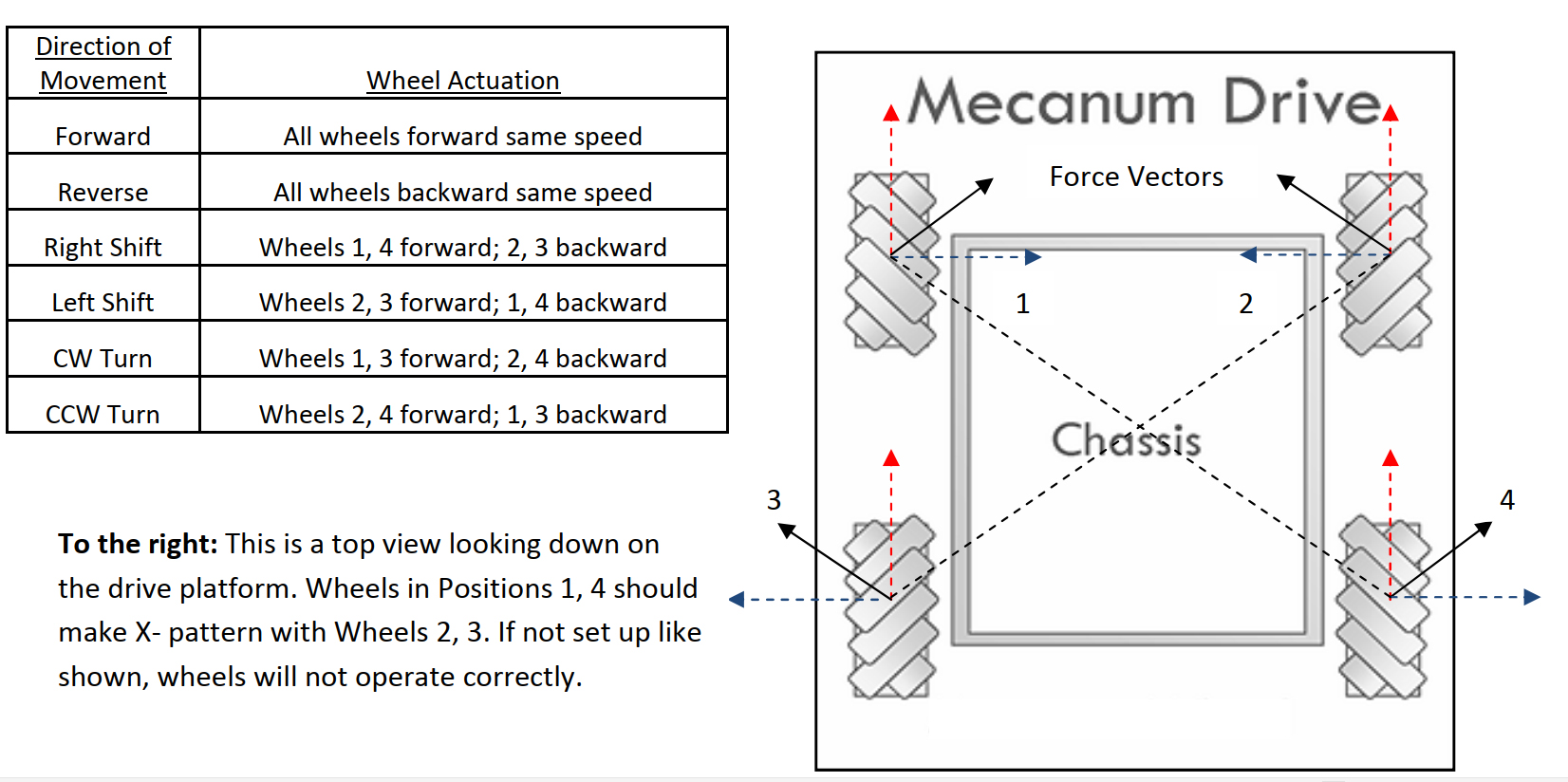
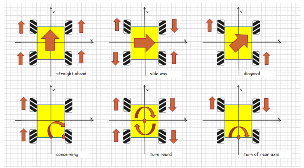
La rueda omnidireccional Mecanum es una rueda muy interesante que permite al coche robot realizar movimientos omnidireccionales (por ejemplo, desplazamiento paralelo a izquierda y derecha).
En este proyecto, mostraremos cómo usar Raspberry Pi para controlar un coche robot con ruedas Mecanum OSOYOO y realizar movimientos básicos como avanzar, retroceder, girar a la izquierda, girar a la derecha, desplazamiento paralelo a la izquierda y desplazamiento paralelo a la derecha.
Esta lección también lo guía a través del ensamblaje del chasis del coche y la conexión de Raspberry Pi y OSOYOO PWM HAT a la placa OSOYOO Model Y. Esta configuración sirve como base para las lecciones siguientes.
Componentes incluidos:
Chasis de coche robótico con ruedas Mecanum OSOYOO x1
Ruedas y motores OSOYOO x4 (ruedas izquierdas x2 / ruedas derechas x2)
Placa Raspberry Pi 4/5 x1 (no incluida en el kit)
Shield OSOYOO PWM HAT x1
Placa controladora de motores OSOYOO Model Y x1
Voltímetro OSOYOO x1
Portapilas OSOYOO x1
Cables jumper hembra-hembra de 6 pines OSOYOO x2
Cable jumper hembra-hembra de 3 pines OSOYOO x1
Cable PnP hembra-hembra de 2 pines XH2.54 OSOYOO x1
Pilas 18650 (3.7V) x2
Cargador de pilas x1
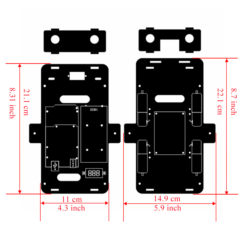
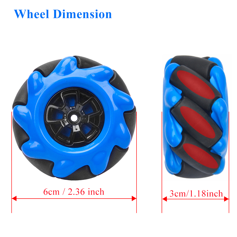
Dimension
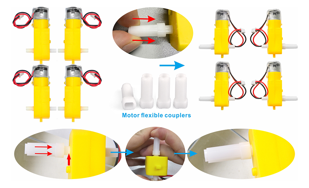
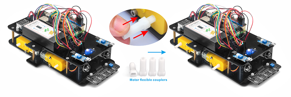
0) Instale el acoplamiento blanco en el motor amarillo según los pasos mostrados en la imagen, asegurándose de que el acoplamiento esté insertado completamente hasta la base.
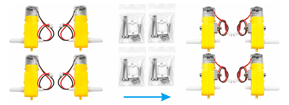
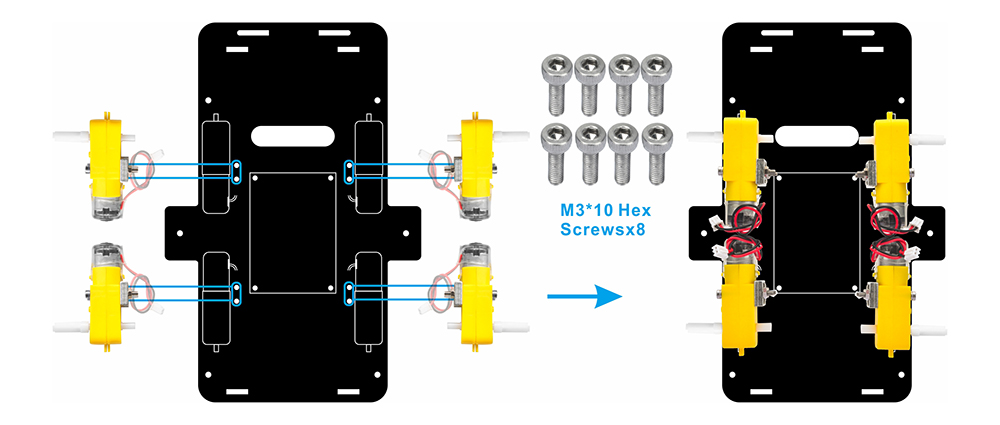
1) Sujete los 4 motores utilizando los soportes metálicos como se muestra. (Asegúrese de que la orientación del motor sea correcta antes de instalar los soportes metálicos.)
2) Fije los 4 motores al chasis inferior del coche utilizando tornillos hexagonales M3*10 y un destornillador hexagonal, como se muestra en la imagen. (Los tornillos necesarios para este paso están incluidos en el paquete de soportes metálicos para motores.)
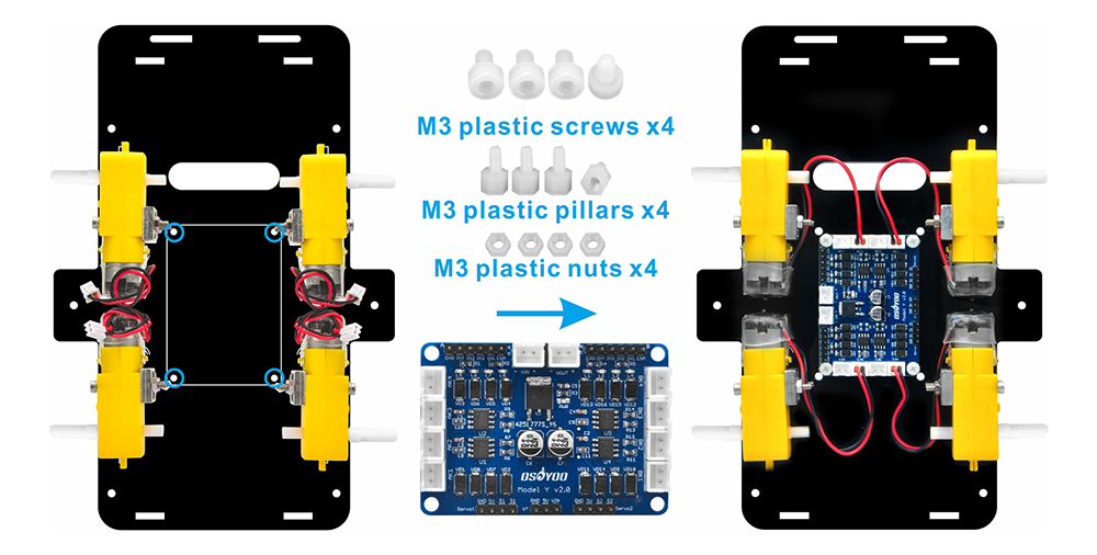
3)Monte la placa controladora OSOYOO Model Y en el chasis inferior del coche utilizando 4 tornillos plásticos M3, espaciadores plásticos y tuercas plásticas (se recomienda instalar los espaciadores plásticos con el extremo macho hacia abajo). Luego, conecte los 4 motores a los sockets K1 y K3 de la placa controladora de motores Model Y, como se muestra en el diagrama.
(Asegúrese de que la placa controladora OSOYOO Model Y esté instalada en la orientación correcta.)
Existen dos modos de instalación para los espaciadores plásticos: A. El extremo macho del espaciador plástico mira hacia abajo. B. El extremo macho del espaciador plástico mira hacia arriba.
.
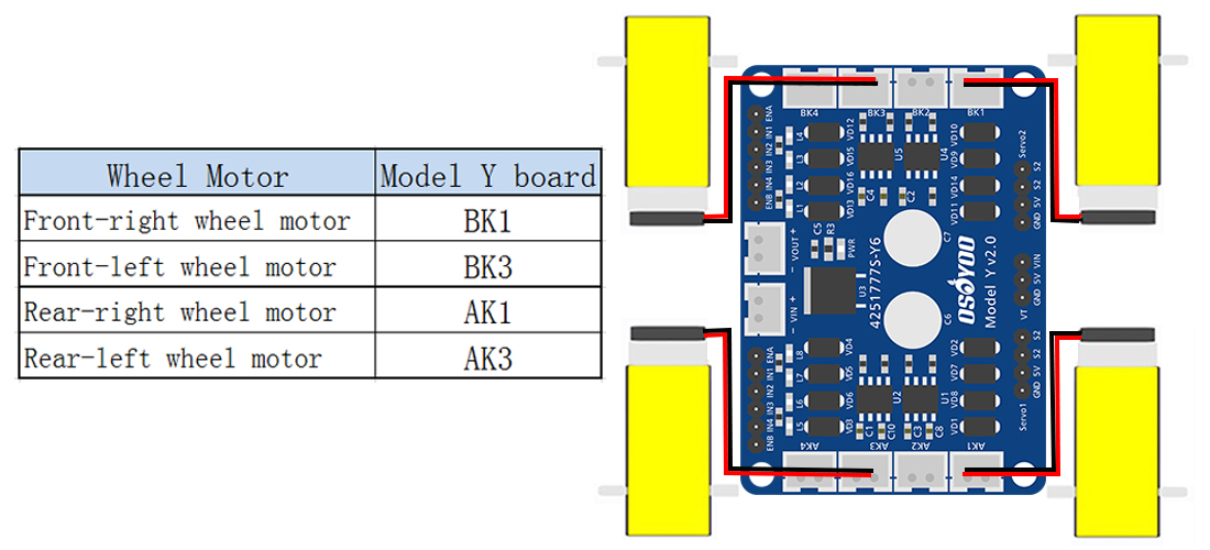
4) Conecte los 4 motores a los sockets K1 y K3 de la placa controladora de motores Model Y, como se muestra en el diagrama.
Acerca de Model Y V2.0 H-Bridge 4-Channel Motor Driver:
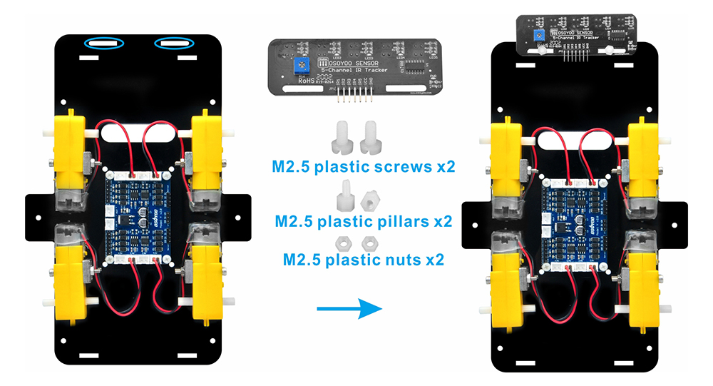
5) Fije el módulo sensor de seguimiento de línea al chasis inferior utilizando dos tornillos plásticos M3, dos espaciadores plásticos M3 y dos tuercas plásticas M3 (se recomienda instalar los espaciadores plásticos con el extremo macho hacia arriba). Asegúrese de que el sensor esté firmemente fijo y correctamente alineado para un funcionamiento preciso.
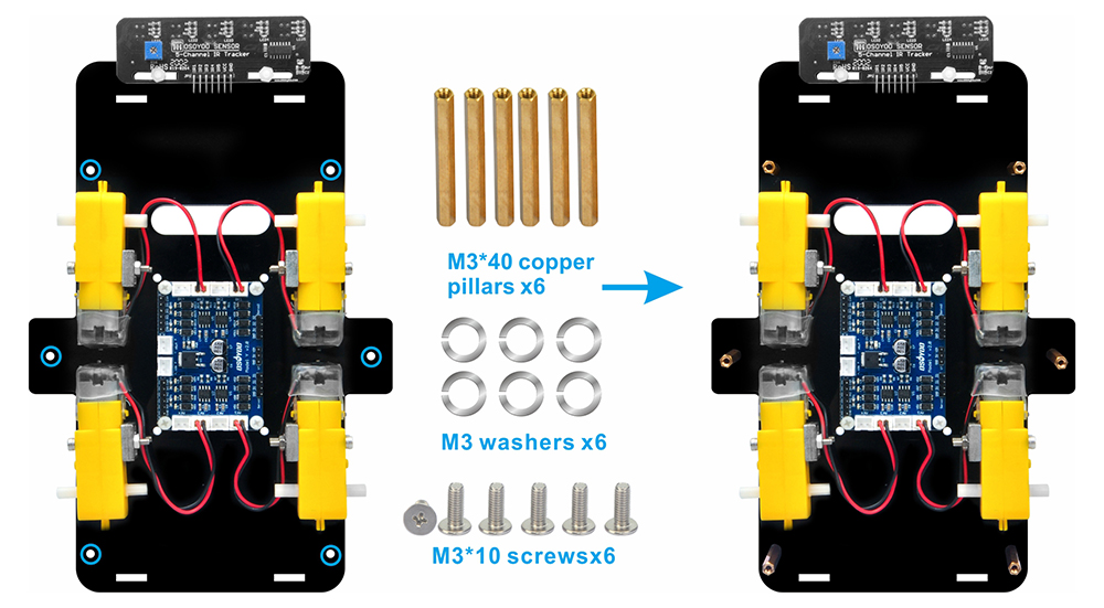
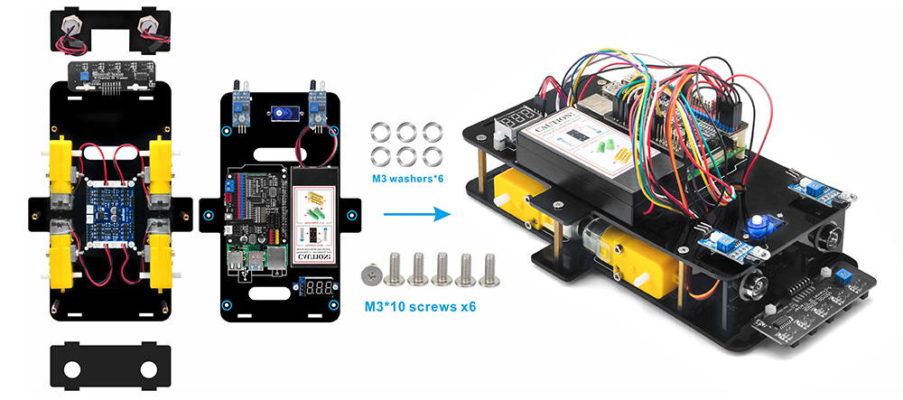
6) Atornille seis espaciadores de cobre M3*40 al chasis inferior utilizando seis tornillos M3*10 y seis arandelas M3. Asegúrese de que los espaciadores estén firmemente fijos para proporcionar un soporte estable al chasis superior.
Deslice la arandela en el tornillo: una arandela distribuye la presión del tornillo y mejora la estabilidad al fijar tornillos en espaciadores metálicos.
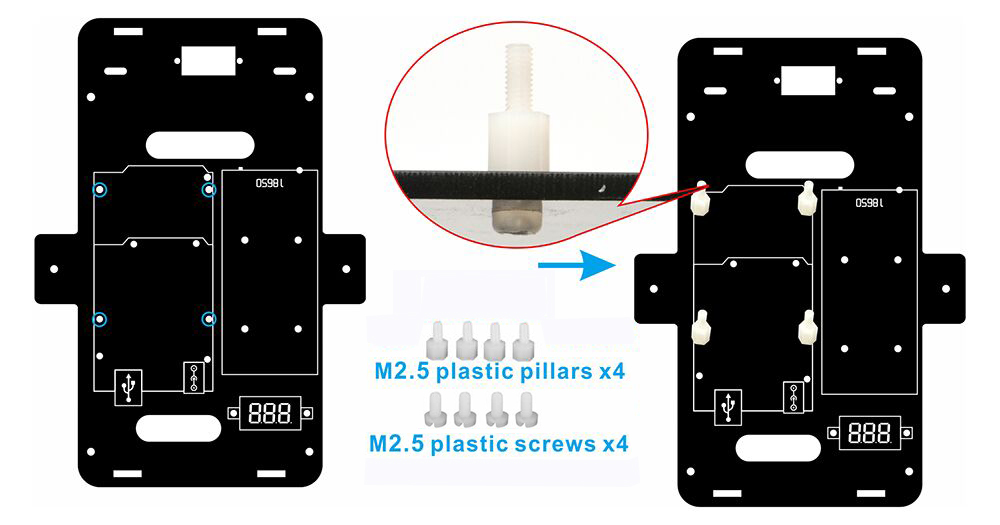
7) El chasis de acrílico tiene orificios de montaje dedicados para la instalación de la placa Raspberry Pi. Instale espaciadores plásticos blancos M2.5*5+6 y tornillos M2.5*5 en estos 4 orificios, como se muestra en la figura a continuación.
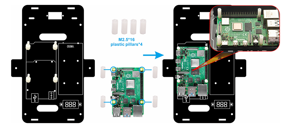
8) Fije la placa Raspberry Pi 4 (no incluida en el paquete) al chasis superior utilizando cuatro espaciadores plásticos M2.5×16.
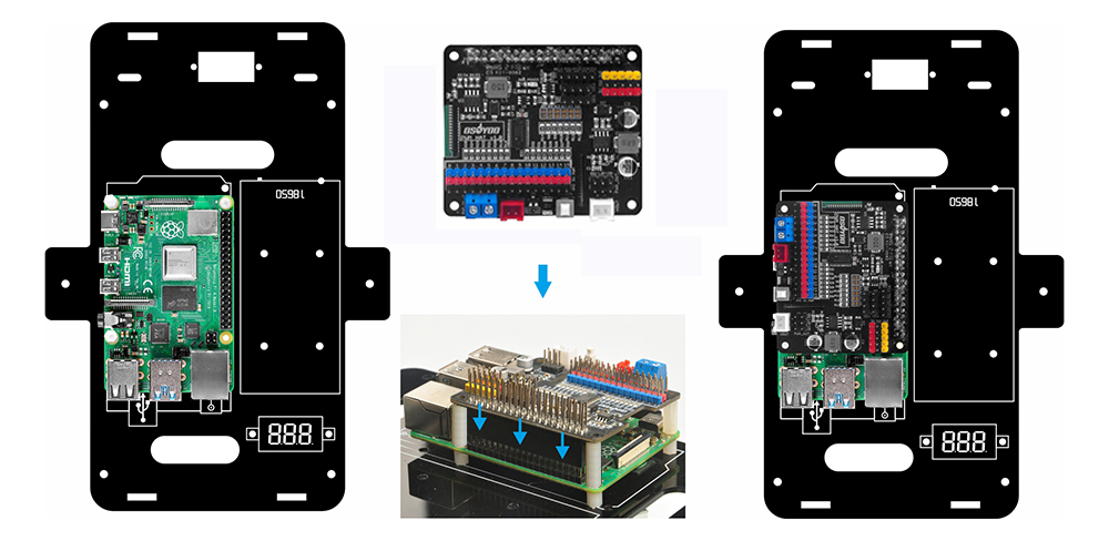
9) Inserte el shield OSOYOO PWM HAT en su placa Raspberry Pi.
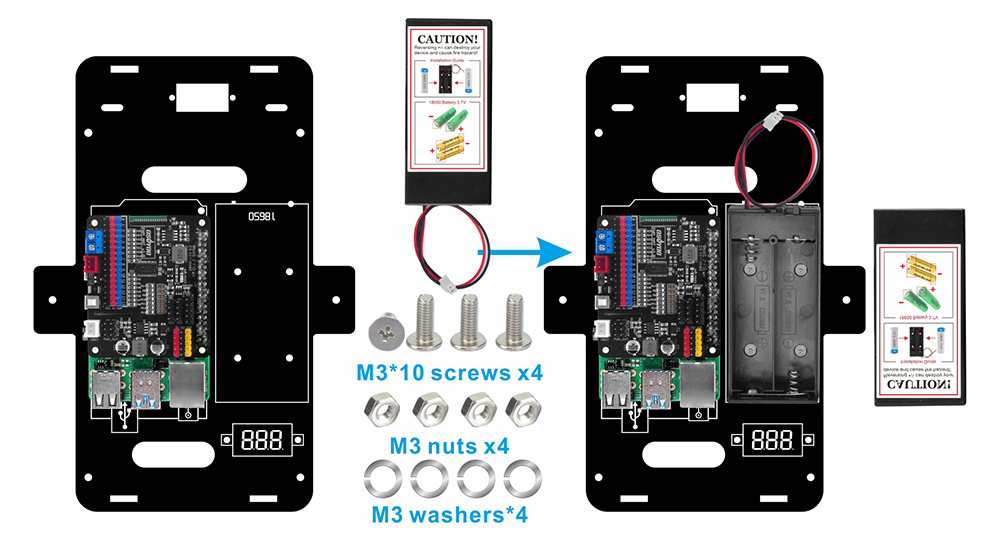
10) Utilice cuatro tornillos M3*10, cuatro tuercas M3 y cuatro arandelas M3 para fijar el portapilas a las marcas designadas en el chasis superior.
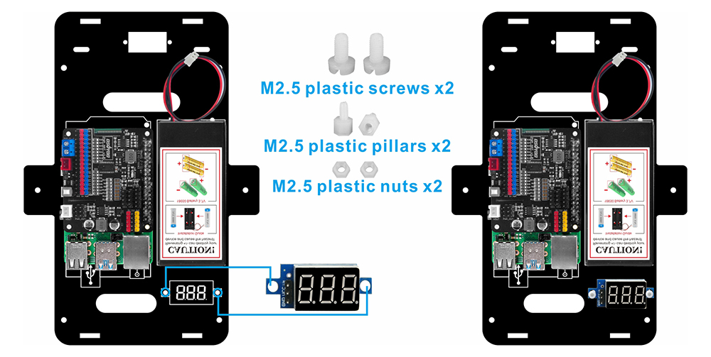
11) Fije el voltímetro a las marcas designadas en el chasis inferior utilizando dos tornillos plásticos M2.5, dos espaciadores plásticos M2.5 y dos tuercas plásticas M2.5. (). (Se recomienda instalar los espaciadores plásticos con el extremo macho hacia arriba.)
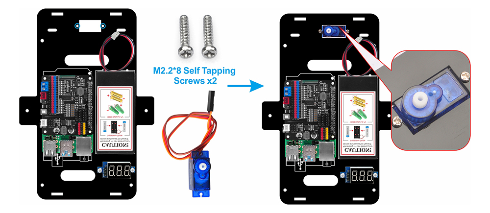
12) Utilizando dos tornillos autorroscantes M2.2*8, monte el servomotor SG90 en la parte frontal del chasis superior.
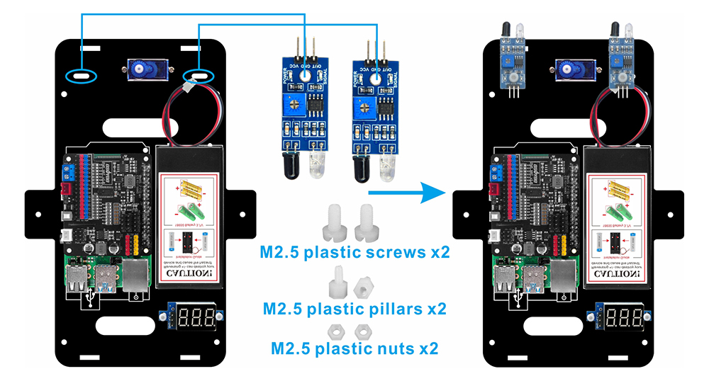
13)Fije dos sensores de distancia IR en la parte frontal del chasis superior utilizando dos tornillos plásticos M2.5, espaciadores plásticos M2.5 y tuercas plásticas M2.5. Para fijar firmemente los sensores, se recomienda instalar los espaciadores plásticos con el extremo macho hacia arriba.Para fijar firmemente los sensores, se recomienda instalar los espaciadores plásticos con el extremo macho hacia arriba.
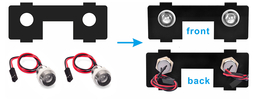
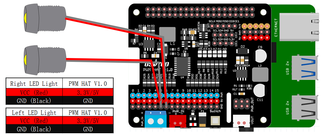
14) Monte dos luces LED en la placa frontal, como se muestra en el diagrama.
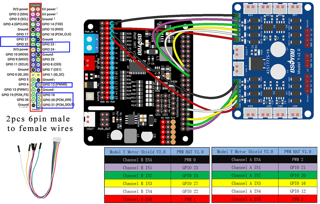
15)Conecte la placa OSOYOO Model Y al shield OSOYOO PWM HAT con 2 cables jumper hembra-hembra de 6 pines como se indica a continuación. Los cables de 6 pines en el Área B deben pasar por el orificio cerca del servomotor SG90, mientras que los otros cables de 6 pines en el Área A deben pasar por el orificio cerca del voltímetro.
Precaución:
Al insertar/retirar este conector de 6 pines en el socket macho de 6 pines del Model Y, sujete el soporte de plástico para realizar la operación. Nunca tire de los cables para extraer el conector del socket, ya que esto dañaría los cables.
.
16)
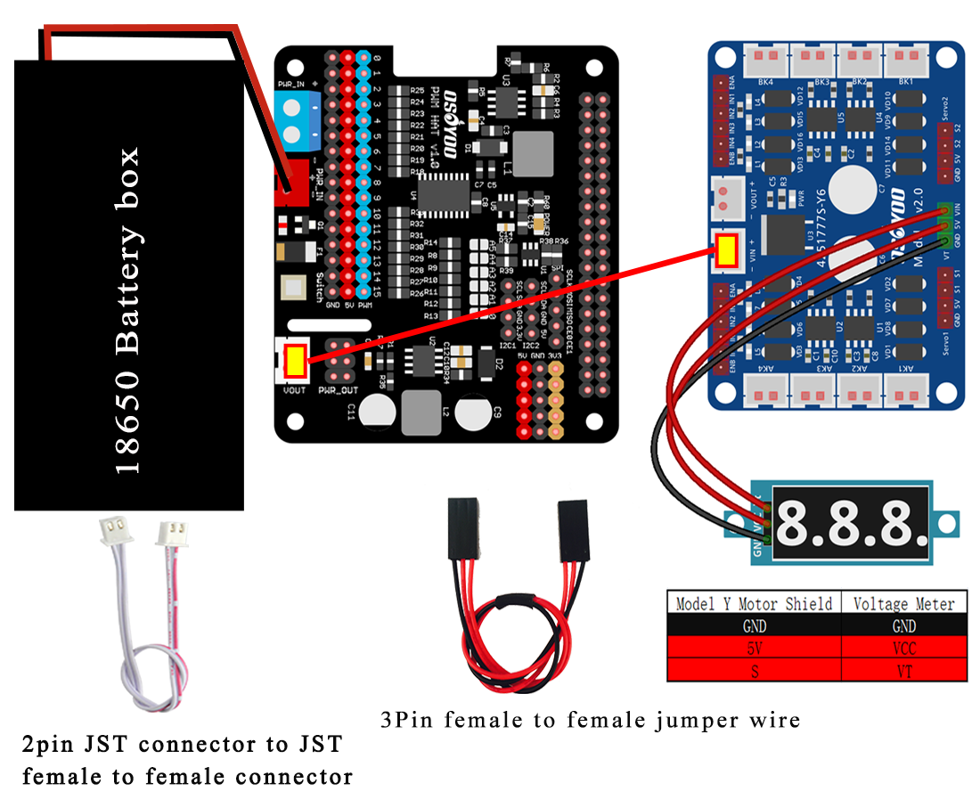
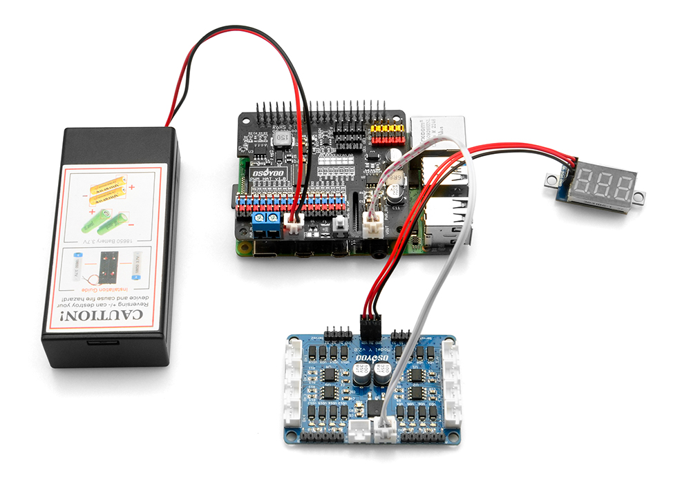
Conecte el voltímetro a la placa OSOYOO Model Y con un cable jumper hembra-hembra de 3 pines, como se muestra en el diagrama de conexión.
Conecte el socket 12V-GND de la placa OSOYOO Model Y al socket VIN-GND con un cable PnP OSOYOO de 2 pines de 20 cm, como se muestra en el gráfico a continuación.
Conecte el portapilas al socket VIN-GND del shield OSOYOO Uart WiFi según el diagrama de conexión a continuación.
17) Monte 2 luces LED en el diafragma transversal frontal.
Conecte los cables rojos (VCC) de las luces LED a los pines 3.3V o 5V, y los cables negros (GND) a los pines GND del shield OSOYOO PWM HAT.
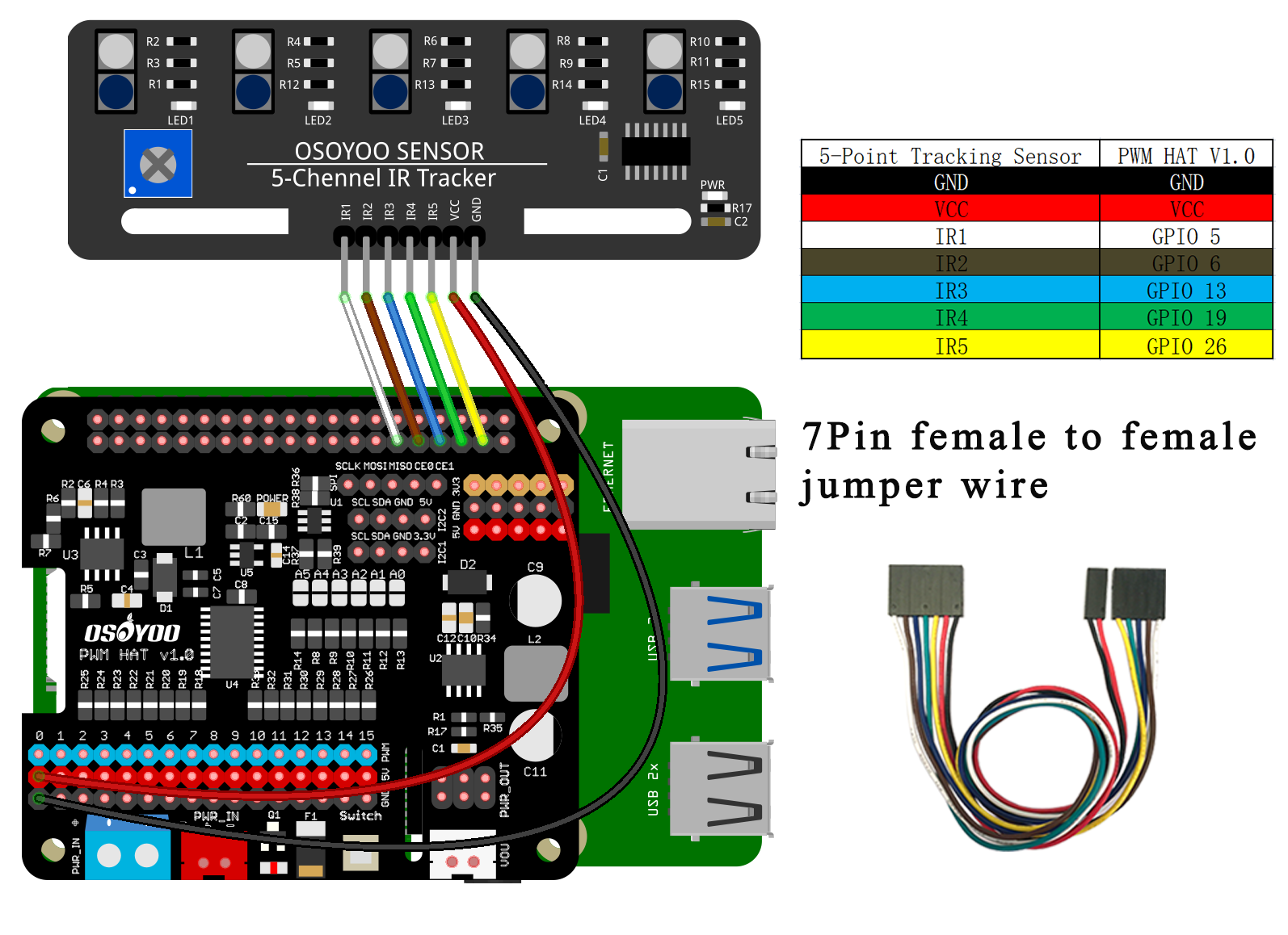
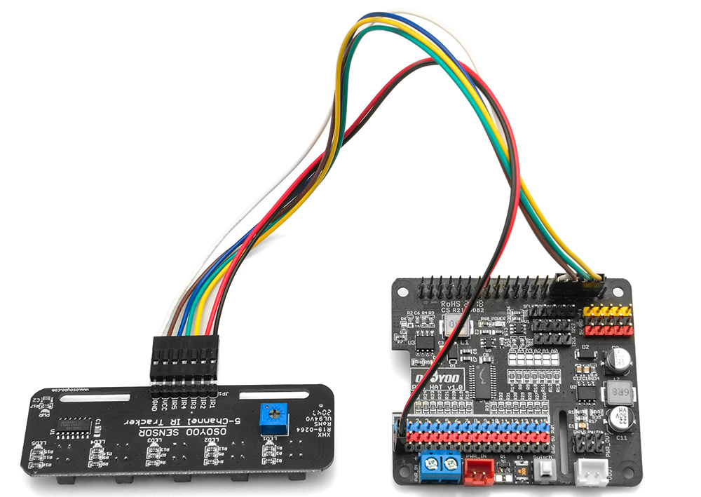
18)Conecte el pin GND-VCC del módulo sensor de seguimiento de línea a los pines GND-5V del shield OSOYOO PWM HAT; conecte los pines IR1, IR2, IR3, IR4, IR5 a los pines GPIO5, GPIO6, GPIO13, GPIO19, GPIO26 con un cable hembra-hembra de 7 pines de 25 cm, como se muestra en la siguiente foto.
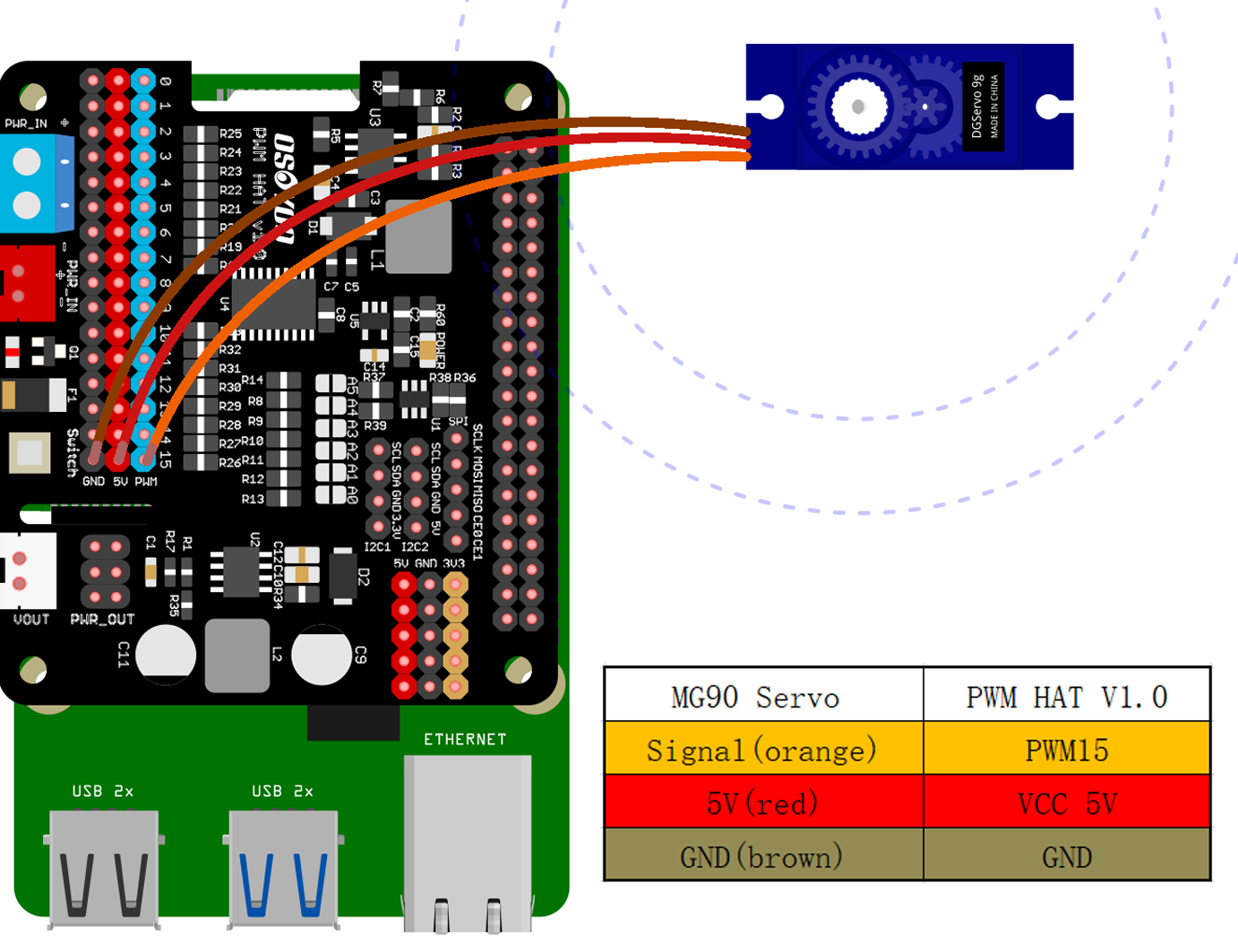
19) Conecte el servomotor SG90, la placa OSOYOO Model Y y el shield OSOYOO PWM HAT como se muestra en el siguiente diagrama.
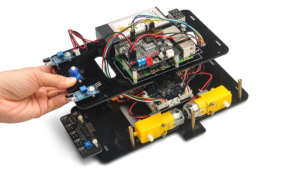
20) Asegúrese de que todas las conexiones de circuito necesarias estén completadas antes de ensamblar el chasis superior e inferior. Fije el chasis superior al chasis inferior con 6 tornillos hexagonales M3*10.
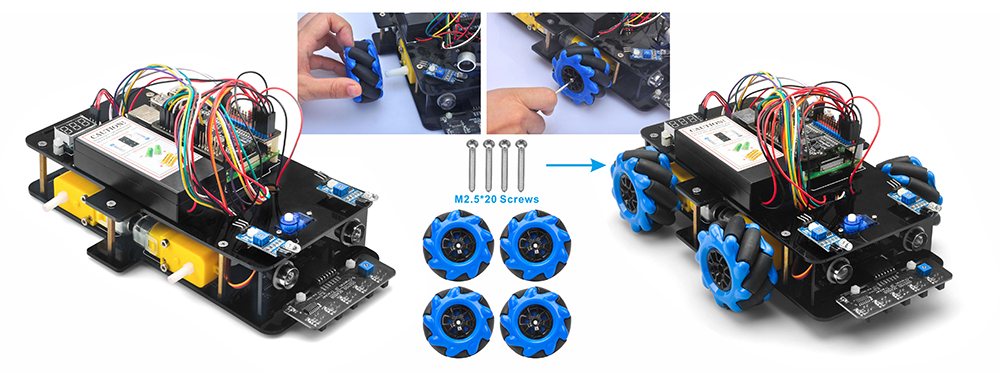
21) Instale 4 acoplamientos flexibles y las ruedas en los motores con 4 tornillos M2.5X20 o M2.6×20.
22) Instale 4 ruedas en los motores con 4 tornillos M2.5X20 o M2.6×20..
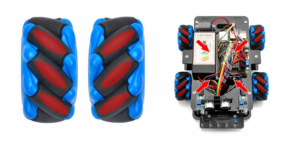
Nota: Existen dos tipos de ruedas. Colóquelas de modo que los rodillos estén inclinados hacia el centro del coche cuando se vean desde arriba.
Existen dos tipos de ruedas Mecanum: ruedas Mecanum izquierda y derecha; la diferencia entre ellas es la orientación de los rodillos. Para una rueda Mecanum tipo A, como se muestra a continuación, los rodillos están orientados desde la parte inferior derecha a la superior izquierda. Los rodillos para las ruedas tipo B se instalan en la dirección opuesta.
Una configuración correcta requiere que cada una de las cuatro ruedas esté colocada como se muestra a continuación, donde el eje de rotación del rodillo superior de cada rueda apunta al centro de la plataforma. Tenga en cuenta que todos los análisis dinámicos y los códigos preescritos se basan en esta configuración.
La instalación del hardware ya está casi completa. Antes de instalar las baterías 18650 en la caja, primero debemos cargar y ejecutar el código de ejemplo en la Raspberry Pi. En la próxima lección explicaremos en detalle cómo cargar y ejecutar el código de ejemplo en la Raspberry Pi.