Overview
This project introduces how to design a voltmeter through the raspberry pi board and voltage sensor , and get the detected data on terminal.
The Component Parts
|
|
|
|
|
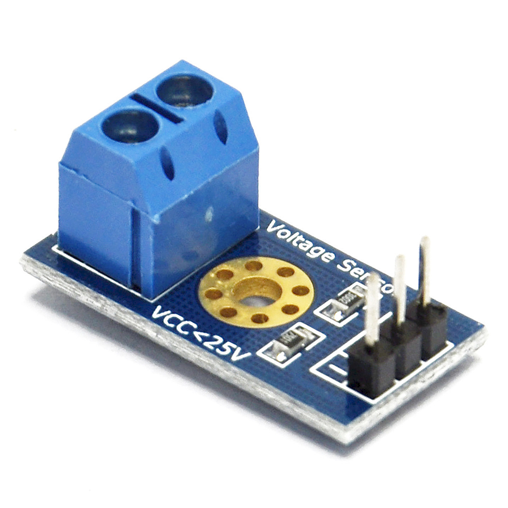
voltage sensor x1 |
|
|
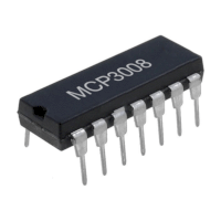
Analog to Digital Converter (ADC) x1 |
|
|
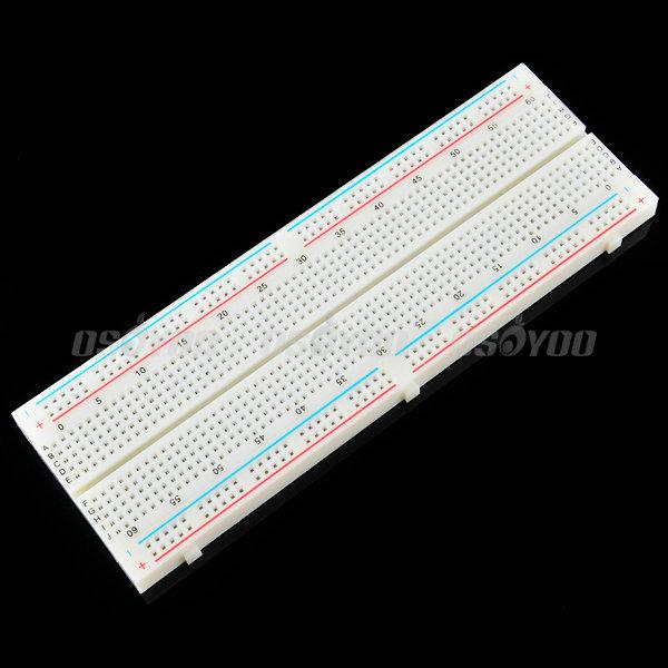
Breadboard x1 |
|
|
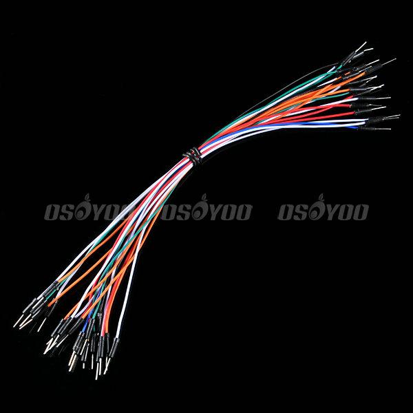
Jumper wire(male to male)
some |
|
|
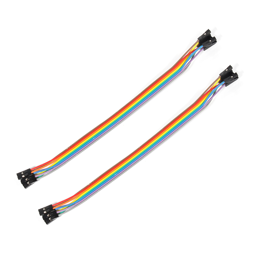
Jumper wire(female to female) some |
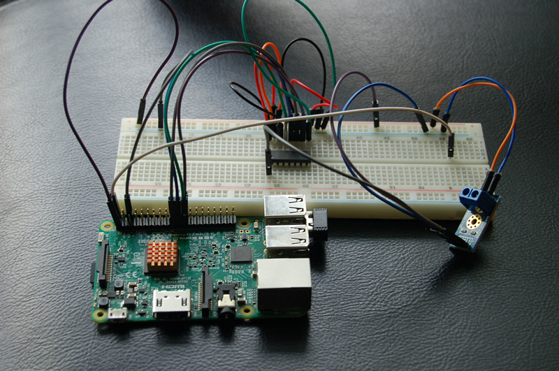
Hardware
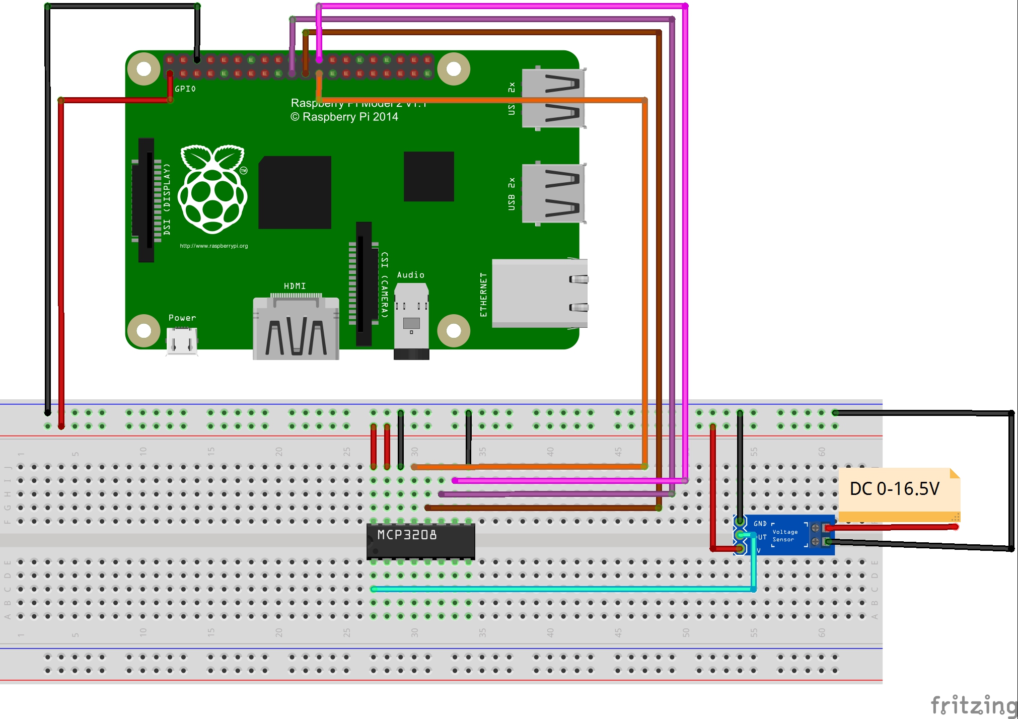
According to resistance divider, the voltage sensor can decreased the voltage to one fifth of the primary voltage. As the working voltage of raspberry pi is 3.3V, you had better input the voltage less than 16.5V (3.3 x 5 = 16.5V).
The output interface of voltage sensor should connect “+” to 3.3V,”-” to GND,”S” to the AD output of ADC. At the other end of voltage sensor, the anode to VCC and the cathode to GND.

As only the digital signal can be processed by raspberry pi, we need to add a analog to digital converter (ADC) to process the analog signal from voltage module. MCP3008 as ADC chip is very common and recommended highly.
Software
You could choose to connect the raspberry pi to monitor, or login in pi via SSH.
1)Write the code
1)enter the following command to create a new file named voltage.py and save this file at direction: /home/pi, and then press enter
sudo nano voltage.py
Enter the sample code in new file, the code can be got by executing shell commands.
sudo wget --no-check-certificate http://osoyoo.com/driver/voltage.py
2)Run python program
sudo python ./voltage.py
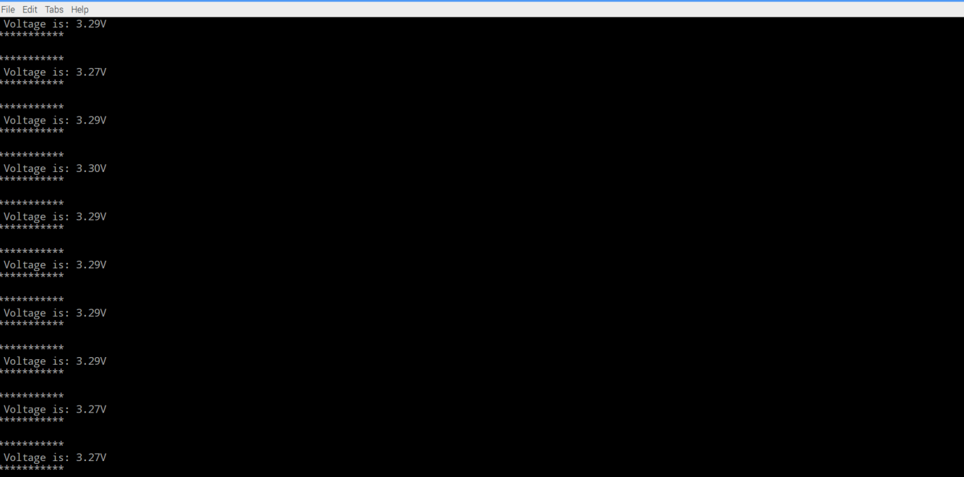
3) Test
Connect the DC port to power supply less 16.5V, the monitor would show the voltage value. For example,you will get the value of 3.29V with the a little allowable error when it connect to 3.3v power supply.