Introduction
The last two lessons have introduced how to program Raspberry Pi to output signal and turn on LED. In this lesson, we will show you how to get input signal from Button switch and trigger output to turn on LED via program.
Software Preparation Note: In this lesson, we remotely control raspberry pi via PuTTy on PC. To learn how to config raspberry pi, please visit lesson 1: getting started with raspberry pi.
Experimental Principle
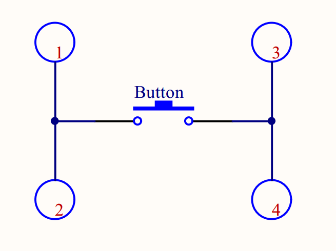
The button is a common component, and works as a switch to turn on or off circuit. The button in our kit has 4 pins, as photo shows:
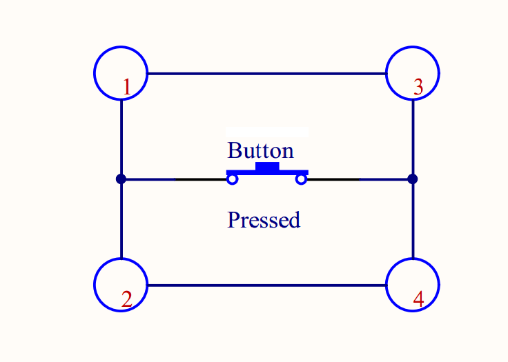
Pin 1 and Pin 2 are conductive, and Pin 3 and Pin 4 are conductive. After pressing button, Pin 1 and Pin 3 become conductive and Pin 2 and Pin 4 become conductive. As photo shows:
Not Press the button
Pressed the button
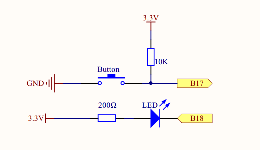
For this project, connect the button to B17, and the LED to B18 as the following circuit graph: B17 for the button in above graph means BCM GPIO#17 or Physical pin#11 or wiringPi#0(zero). B18 for the LED in above graph means BCM GPIO#18 or Physical pin#12 or wiringPi#1. Note: B means BCM(Broadcom pin number). If you don’t know what is BCM pin#, Physical pin#, wiringPi#, please review our lesson 2: Introduction Of Raspberry Pi GPIO
If the button is not pressed , B17(wiringPi#0(zero)) input voltage is pulled up to 3.3V through 10K resistor . Once our sample code reads high voltage from B17, it will output high level to B18(wiringPi#1) which will turn off LED.
If the button is pressed , the B17(wiringPi#0(zero)) input is set to zero(connect to GND) , sample code will output zero voltage to B18(wiringPi#1) which turns the LED on.
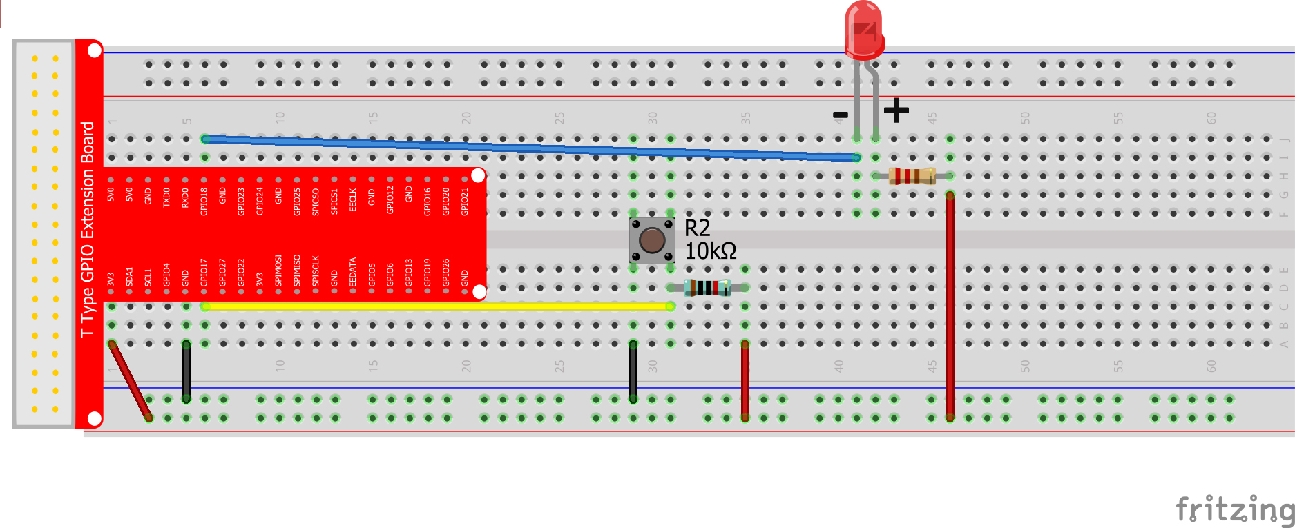
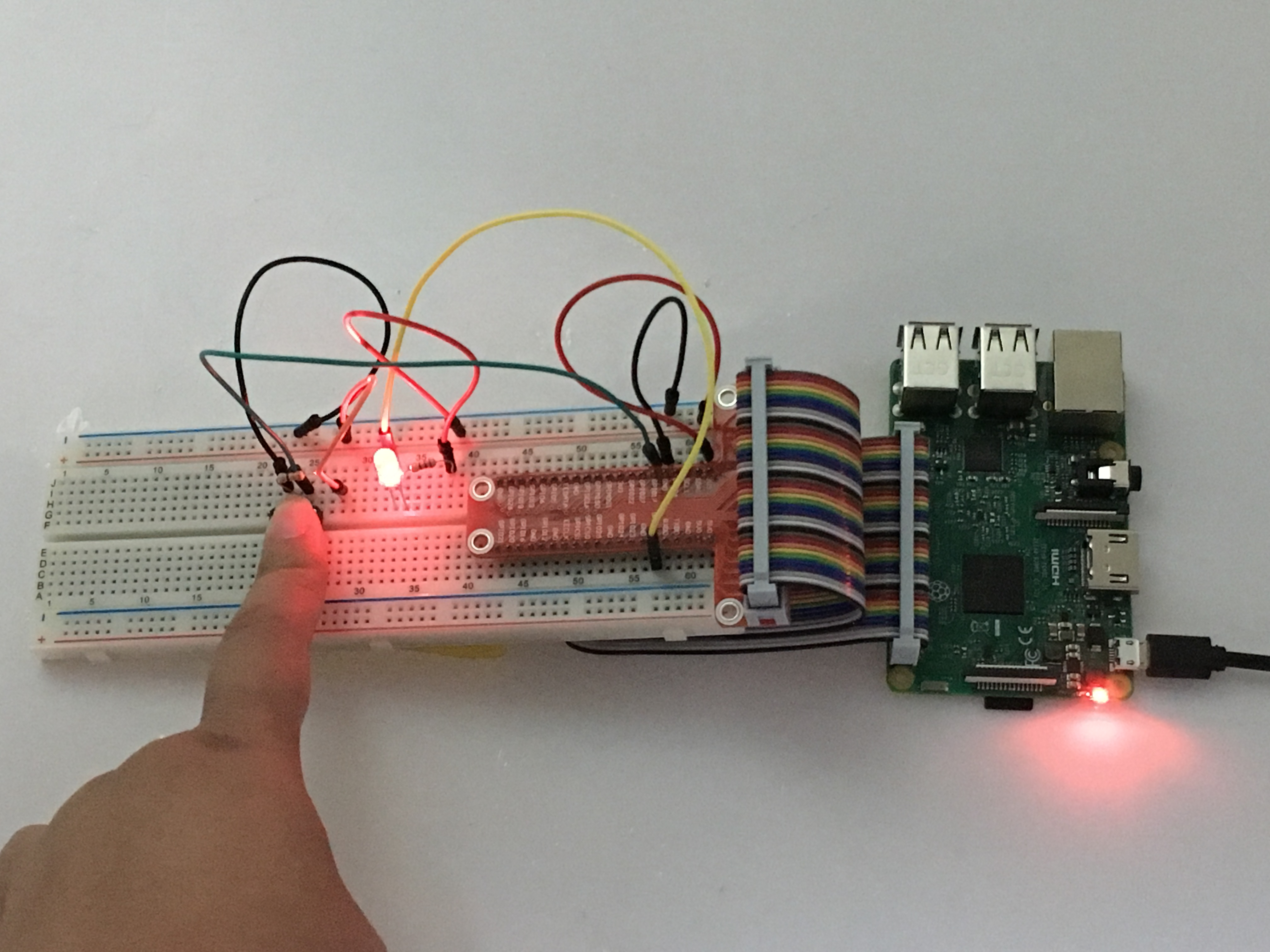
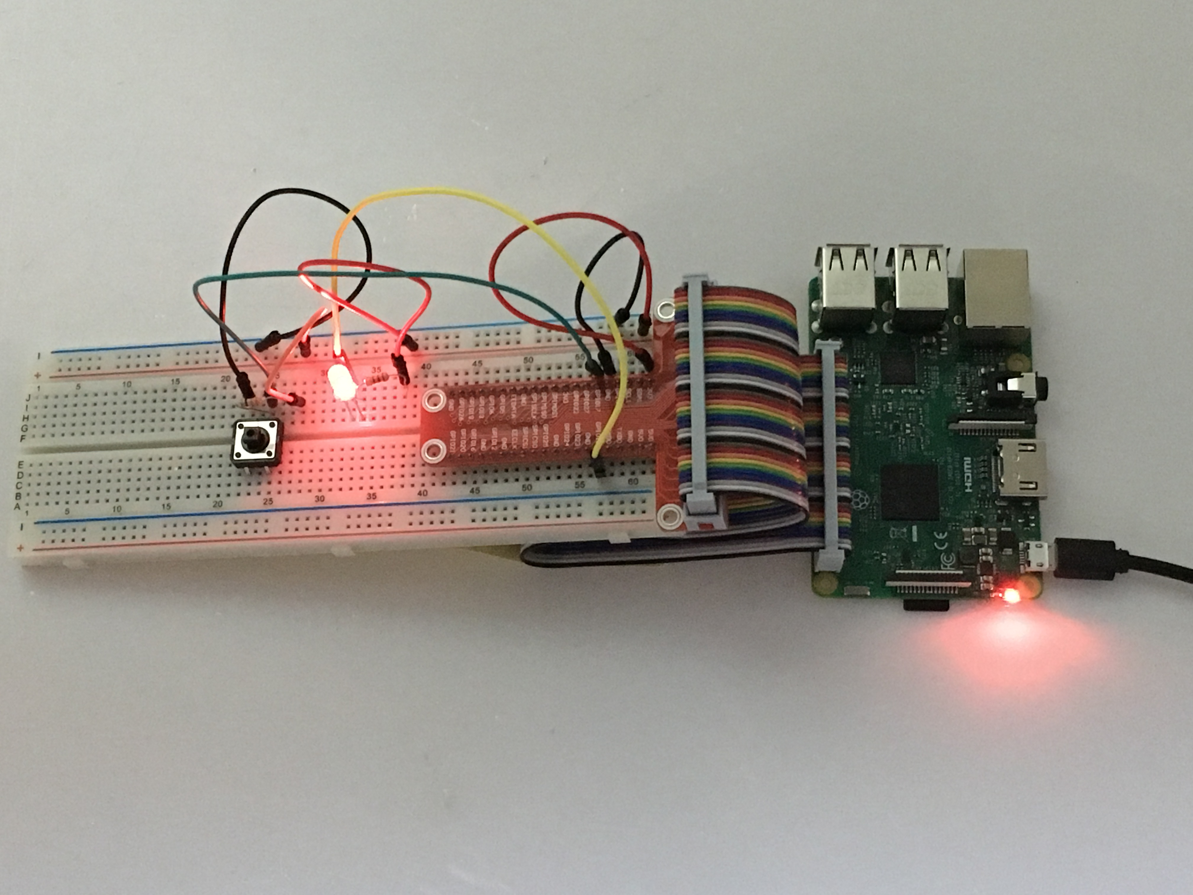
Hardware Setup
Assembling the Circuit as followed Connection Graph
Software
We’ll provide two kinds of codes for C language users and Python language users.
For C Language users,please follow the next steps:
Note: please be sure installation wiringpi. Click here, you can learn more about how to check whether installing wiringpi and install wiringpi
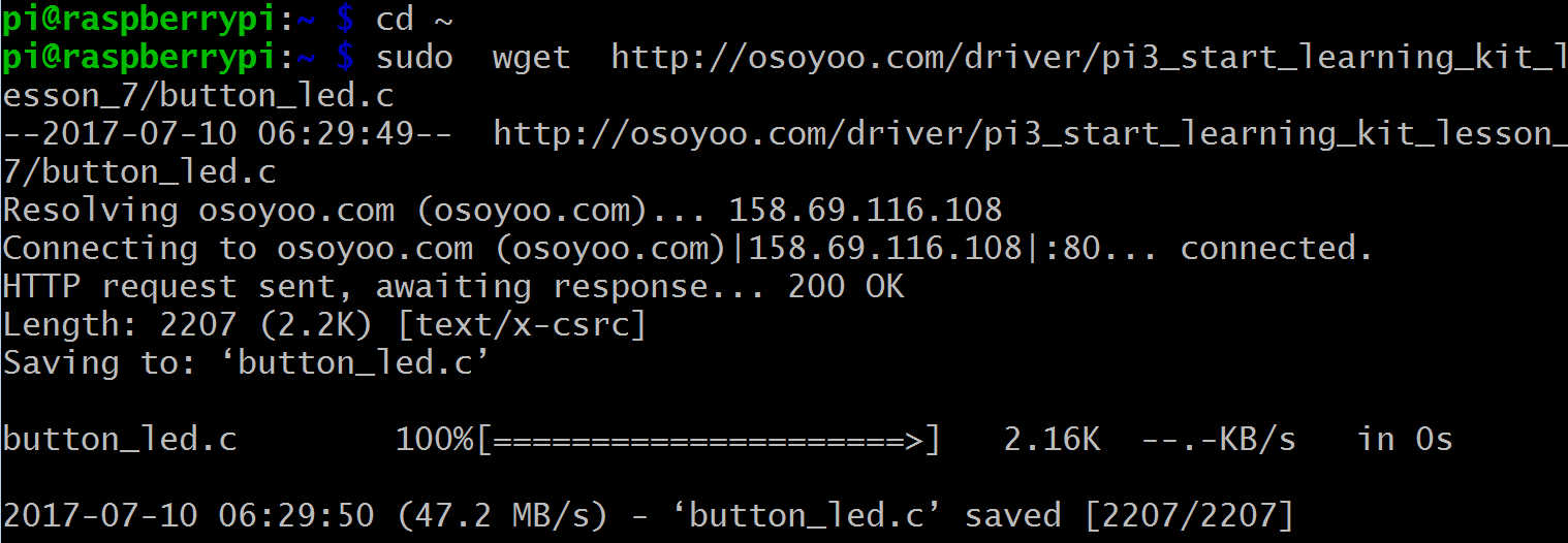
Step 1) Download sample code button_led.c from osoyoo.com by typing following commands in terminal: pi@raspberry:~ $ cd ~ pi@raspberry:~ $ sudo wget http://osoyoo.com/driver/pi3_start_learning_kit_lesson_7/button_led.c
Note:
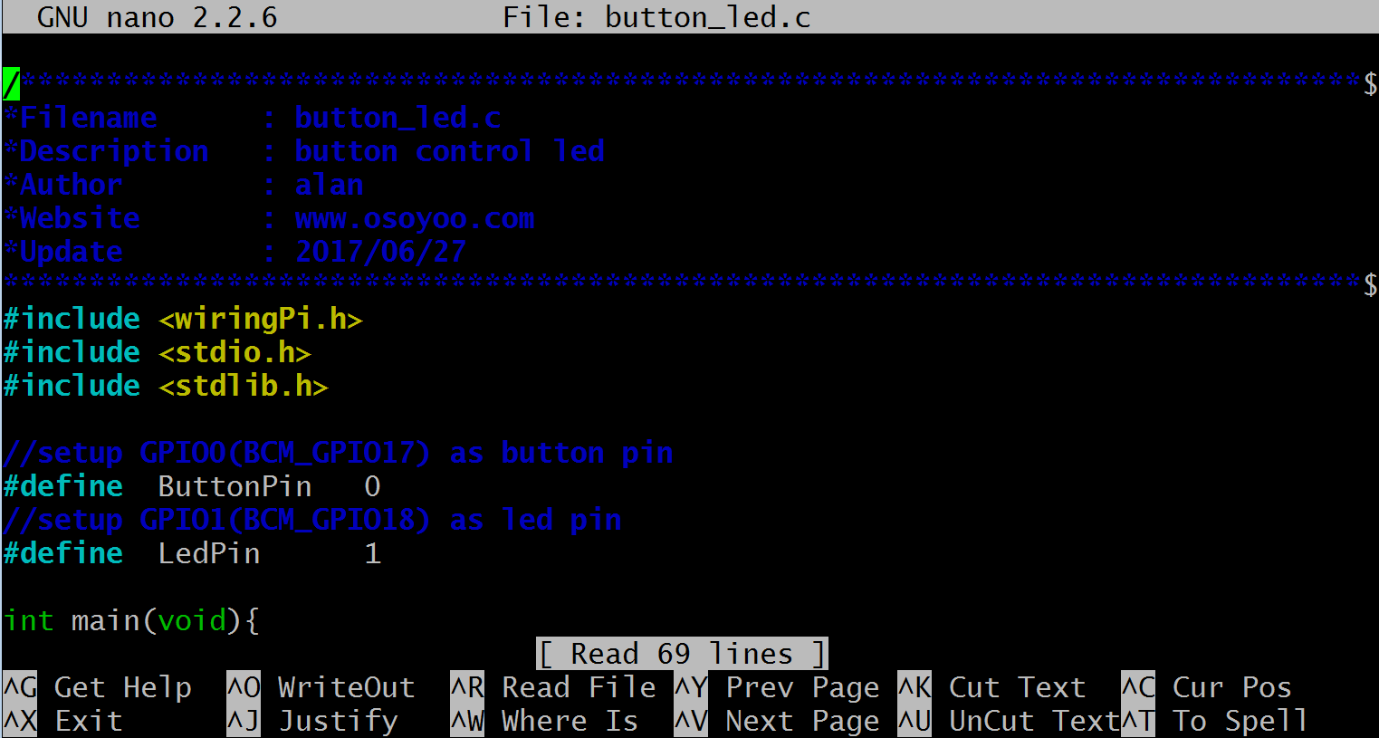
If you want to customize the sample code file , you can use nano editor to edit source code by typing following command in terminal: pi@raspberry:~ $ sudo nano button_led.c
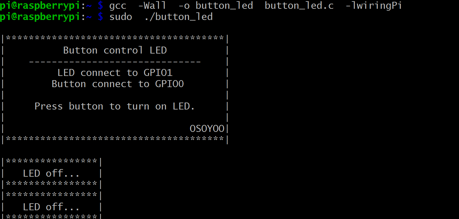
Step 2) Compile code pi@raspberry:~ $ gcc -Wall -o button_led button_led.c -lwiringPi Note: gcc: is GNU Compiler Collection. If you want to write your own C code and compile to run it, you need to master gcc. for more information about gcc, please visit here -Wall: to get more error when compile the code -o: to name the compiled file. You can name the file as your like. here we name as button_led button_led.c: means the original file which is compiled -lwiringPi: is to load the library wiringPi (l is short for library)
Step 3) Run the program pi@raspberry:~ $ sudo ./button_led
Step 4) Program result
Once program starts running, the terminal will show print message as code firstly, and then show LED off. When pressing the button, the LED will turn on and the terminal shows LED On. when releasing the button, the LED will turn off and the terminal shows LED Off. If you wan’t to stop the program, please go to terminal and type command: Ctrl + C.
C languange sample code and Explanation comments
#include < wiringPi.h>
#include < stdio.h>
#include < stdlib.h>

//setup wirping#0(BCM_GPIO17) as Button pin
#define  ButtonPin   0
//setup wiringPi#1(BCM_GPIO18) as LED pin
#define  LedPin      1

int main(void){
    // When initialize wiring failed, print messageto screen
    if(wiringPiSetup() == -1){
        printf("setup wiringPi failed!");
        exit(1);
    }
    //set LedPin BCM18 working at OUTPUT mode
    pinMode(LedPin, OUTPUT);
    //set ButtonPin BCM17 working at INPUT mode
    pinMode(ButtonPin, INPUT);

    // Pull up to 3.3V,make GPIO1 a stable level
    pullUpDnControl(ButtonPin, PUD_UP);

    printf("\n");
    printf("|**************************************|\n");
    printf("|          Button control LED          |\n");
    printf("|    ------------------------------    |\n");
    printf("|         LED connect to GPIO1         |\n");
    printf("|        Button connect to GPIO0       |\n");
    printf("|                                      |\n");
    printf("|     Press button to turn on LED.     |\n");
    printf("|                                      |\n");
    printf("|                                OSOYOO|\n");
    printf("|**************************************|\n");
    printf("\n");

    digitalWrite(LedPin, HIGH);
    printf("|****************|\n");
    printf("|   LED off...   |\n");
    printf("|****************|\n");

    for(;;){
        // Indicate that button has pressed down
        if(digitalRead(ButtonPin) == 0){
            // Led on
            digitalWrite(LedPin, LOW);
            printf("|****************|\n");
            printf("|   ...LED on    |\n");
            printf("|****************|\n");
            delay(400);
        }
        else{
            // Led off
            digitalWrite(LedPin, HIGH);
            printf("|****************|\n");
            printf("|   LED off...   |\n");
            printf("|****************|\n");
            delay(400);
        }
    }
    return 0;
}
For Python Language users, please follow the below step:
When programming with Python language , normally we use GPIO library called RPi.GPIO which comes with Rasbian Jessie OS. Click here, and you can learn more about RPI.GPIO and Python.
Step 1) Download sample python code to /home/pi by following terminal command: pi@raspberry:~ $ cd ~ pi@raspberry:~ $ sudo wget http://osoyoo.com/driver/pi3_start_learning_kit_lesson_7/button_led.py
Note:
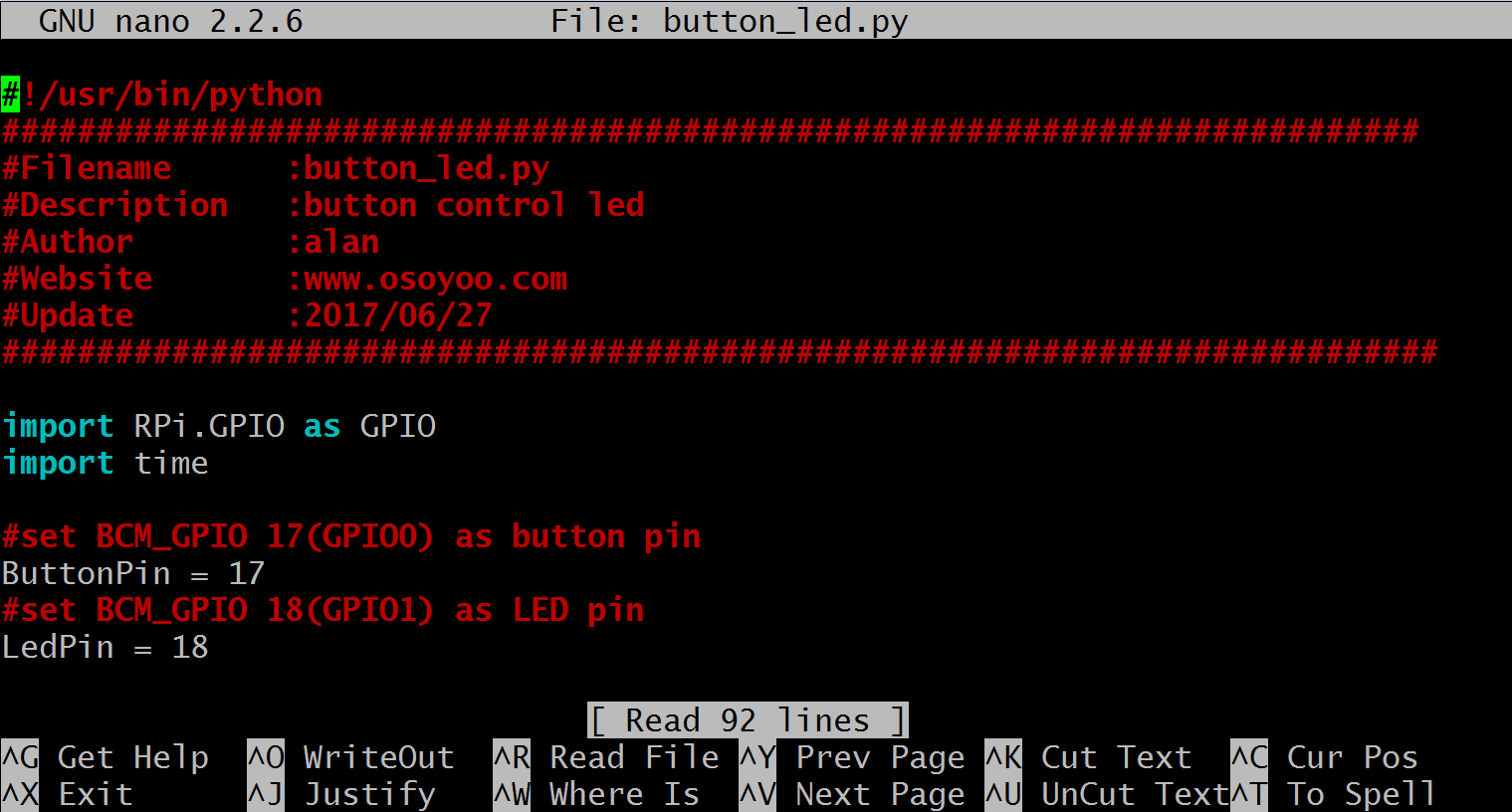
If you want to customize the sample code file , you can use nano editor to edit source code by typing following command in terminal: pi@raspberry:~ $ sudo nano button_led.py
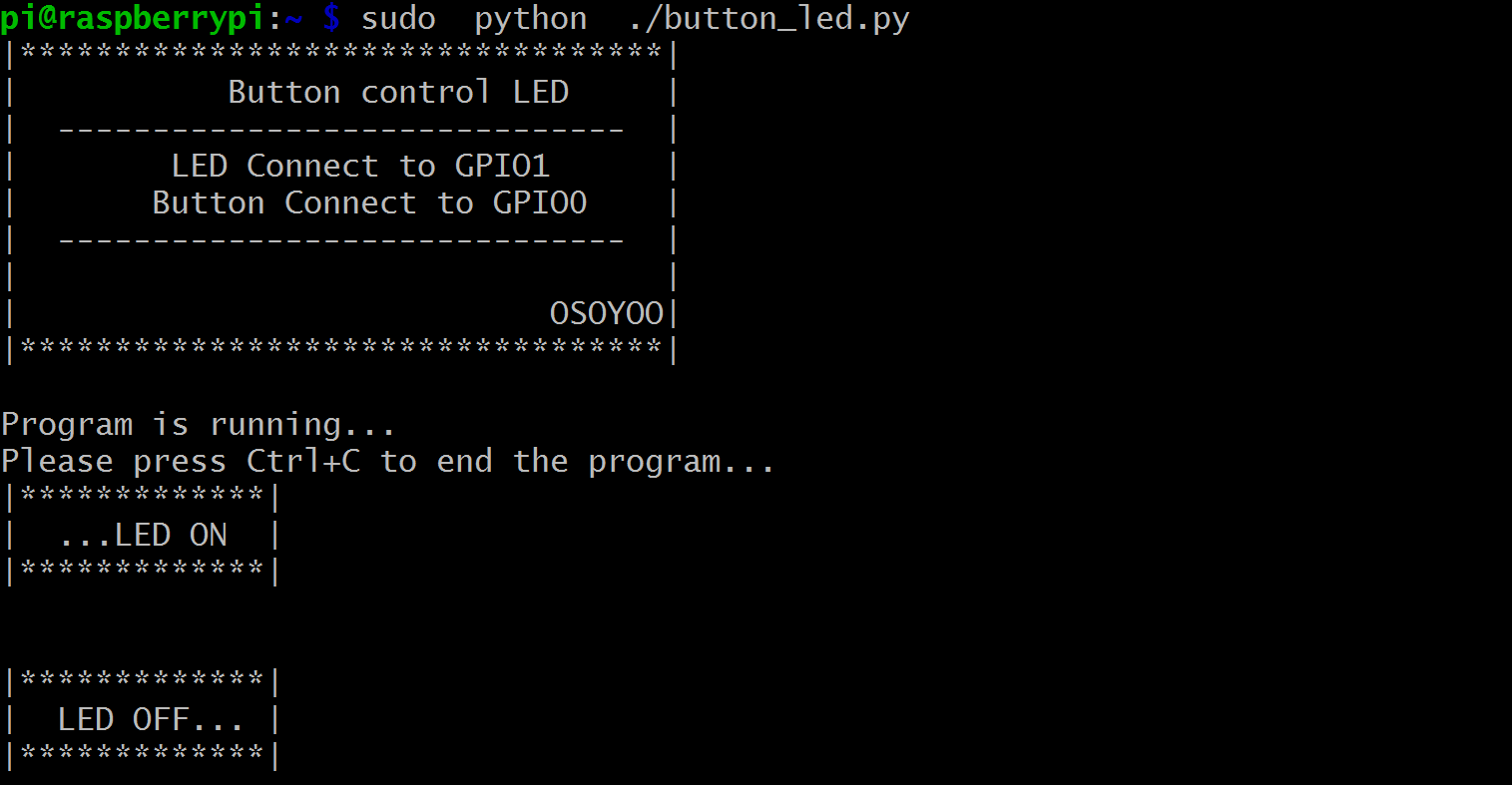
Step 2) Run program pi@raspberry:~ $ sudo python ./button_led.py
Step 3) Program result
Once program starts running, the terminal will show print message as code firstly. When pressing the button, the LED will turn on and the terminal shows LED On. when pressing the button again, the LED will turn off and the terminal shows LED Off. If you wan’t to stop the program, please go to terminal and type command: Ctrl + C.
Python Code Explanation
import RPi.GPIO as GPIO
import time

#set BCM_GPIO 17(GPIO0) as button pin
ButtonPin = 17
#set BCM_GPIO 18(GPIO1) as LED pin
LedPin = 18

#set led status to True(OFF)
led_status = True
a. Import Python GPIO Library and time library. The GPIO library is the library for interacting with the GPIO in Python. It does the job of simplifying the process. The time library is there so we can put a delay in, otherwise the blink might be too fast to notice.Define LED and button GPIO (Here we use BCM#) and set True(3.3V) as the LED’s initial status.
 def setup():
    GPIO.setwarnings(False)
    #set the gpio modes to BCM numbering
    GPIO.setmode(GPIO.BCM)
    #set all LedPin's mode to output,and initial level to HIGH(3.3V)
    GPIO.setup(LedPin,GPIO.OUT,initial=GPIO.HIGH)
    #set ButtonPin's mode to input,and pull up to high(3.3v)
    GPIO.setup(ButtonPin,GPIO.IN,pull_up_down = GPIO.PUD_UP)
    #set up a falling detect on ButtonPin,and callback function to ButtonLed
    GPIO.add_event_detect(ButtonPin,GPIO.FALLING,callback = ButtonLed)
    pass
b. pinMode(ButtonPin, INPUT) and pullUpDnControl(ButtonPin, PUD_UP) set ButtonPin pull-up input. The program gets a level from buttonpin times and times. While the button is pressed, the program gets low level, and it output low level to LEDPin, and then the LED will turn on. Else, the LedPin gets high level, and the LED turn off. setup function set LEDPin as output mode, and button as pull-up input mode and set up a falling detect on ButtonPin. When raspberry pi detects ButtonPin falling off, the program will go back callback function to implement breakoff code.
 def ButtonLed(ev=None):
    global led_status
    # Switch led status(on-->off; off-->on)
    led_status = not led_status
    GPIO.output(LedPin, led_status)
    if led_status:
        print('|*************|')
        print('|  LED OFF... |')
        print('|*************|')
        print('\n')
    else:
        print('|*************|')
        print('|  ...LED ON  |')
        print('|*************|')
        print('\n')
c. In callback function, LedPin level is reversed. It means, when LedPin level is off, the LED is on, and when LedPin level is on, the LED is off.
 def main():
    # Print messages
    print_message()
    while True:
        # Don't do anything.
        time.sleep(1)
d. main function works as nothing except waiting for breakoff.