Software Preparation Note: In this lesson, we remotely control raspberry pi via PuTTy on PC. To learn how to config raspberry pi, please visit lesson 1: getting started with raspberry pi.
Work Principle
A photoresistor is a light-controlled variable resistor. The resistance of a photoresistor decreases with increasing light intensity.
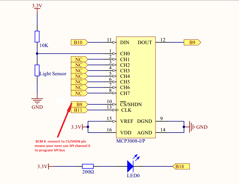
In this project we use MCP3008 ADC to read the photoresistor voltage value which changes with light. the MCP3008 convert the analog voltage value to digital signal(binary value) and sent it to the Pi. Then Pi changes PWM input value to control the LED brightness. Circuit Graph:
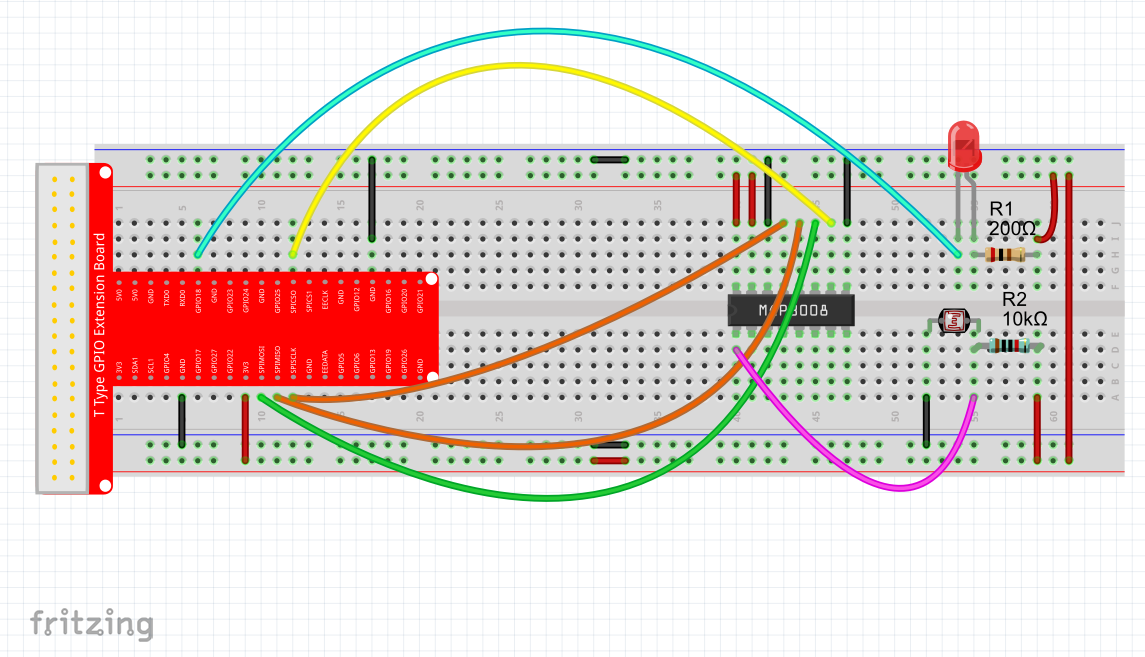
Hardware Setup
Sample code
we’ll provide two kinds of codes for C language users and Python language users.
For C language users ,please take following steps:
Note: If you have not installed wiringPi library. Please install it as per our Lesson 3
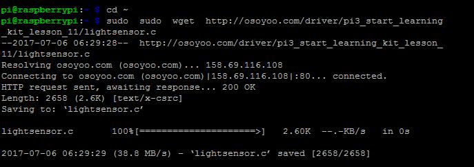
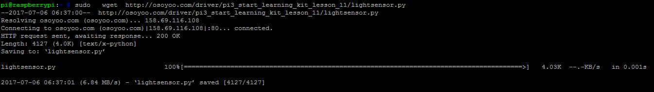
1) Download the sample code from osoyoo by typing the following command:
Note: If you want to customize the sample code file , you can use nano editor to edit source code by typing following command in terminal: sudo nano lightsensor.c
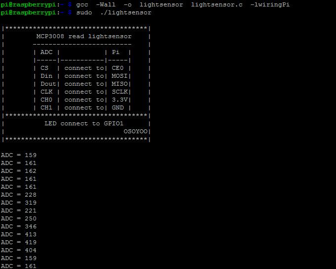
2) Compile Code
gcc -Wall -o lightsensor lightsensor.c -lwiringPi
3) Run program
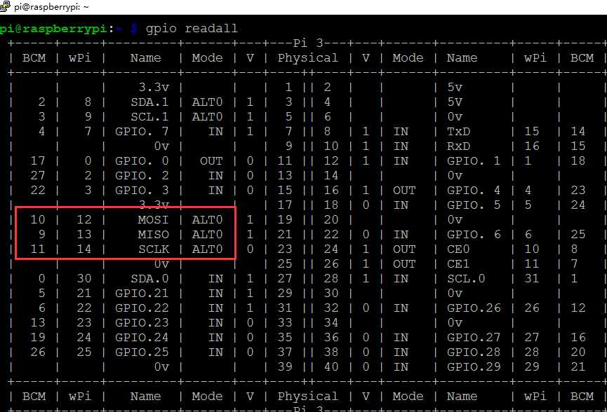
A)Before running the program, check MOSI, MISO, SCLK(B10, B9, B11) work mode is ALT0(alternative functions) by typing terminal command:gpio readall If the mode is not ALTO, Please running the terminal command as followed:
gpio -g mode 9 alt0
gpio -g mode 10 alt0
gpio -g mode 11 alt0
B) Run the program
sudo ./lightsensor
4) Test Result
When program is executed, the terminal will show print message as code firstly,then show the photoresistor ADC value(voltage). when the photoresistor is shaded, the LED brightness will increase, when photoresistor is unshaded, the LED brightness will decrease.
Sample Code and Explanation comments
#include < unistd.h >
#include < stdint.h >
#include < string.h >
#include < errno.h >
#include < wiringPi.h >
#include < stdio.h >
#include < stdlib.h >
#include < wiringPiSPI.h >

//pin 1(BCM GPIO 18) is PWM  port
#define  LEDPIN   1
//binary number 1000 (decimal 8) is analog channel prefix
#define CHAN_CONFIG_SINGLE  8

//About SPI channel, read https://osoyoo.com/?p=7612
//since B8 connect to CS/SHDN pin, we need select SPI Channel to 0
#define SPICHANNEL          0

//our light sensor connect to MCP3008 CH0, we set annanalog channel to 0
#define ANALOGCHANNEL       0
static int myFd ;

void spiSetup (int spiChannel)
{
    if ((myFd = wiringPiSPISetup (spiChannel, 10000)) < 0)
    {
        fprintf (stderr, "Can't open the SPI bus: %s\n", strerror (errno)) ;
        exit (EXIT_FAILURE) ;
    }
}

int myAnalogRead(int spiChannel,int channelConfig,int analogChannel)
{
    if(analogChannel7)
        return -1;
    unsigned char buffer[3] = {1}; // start bit
    buffer[1] = (channelConfig+analogChannel) << 4;
    wiringPiSPIDataRW(spiChannel, buffer, 3);
    return ( (buffer[1] & 3 ) << 8 ) + buffer[2]; // get last 10 bits
}

void print_info()
{
    printf("\n");
    printf("|************************************|\n");
    printf("|        MCP3008 read lightsensor    |\n");
    printf("|       -------------------------    |\n");
    printf("|       | ADC |           | Pi  |    |\n");
    printf("|       |-----|-----------|-----|    |\n");
    printf("|       | CS  | connect to| CE0 |    |\n");
    printf("|       | Din | connect to| MOSI|    |\n");
    printf("|       | Dout| connect to| MISO|    |\n");
    printf("|       | CLK | connect to| SCLK|    |\n");
    printf("|       | CH0 | connect to| 3.3V|    |\n");
    printf("|       | CH1 | connect to| GND |    |\n");
    printf("|************************************|\n");
    printf("|          LED connect to GPIO1      |\n");
    printf("|                              OSOYOO|\n");
    printf("|************************************|\n");
    printf("\n");

}

int main()
{
  int adc;
  if(wiringPiSetup()<0)
    {
      printf("setup wiringPi failed!\n");
            printf("please check your setup\n");
            exit(1);
    }
  spiSetup(SPICHANNEL);
  pinMode(LEDPIN,PWM_OUTPUT);
  print_info();

  for(;;)
  {
      //read voltage value from analog CH0 pin data from SPI channel 0
      adc = myAnalogRead(SPICHANNEL,CHAN_CONFIG_SINGLE,ANALOGCHANNEL);
            printf("ADC = %d\n",adc);
      //adc is a value between 0 to 1023, 1023 means max vref value 3.3V
      pwmWrite(LEDPIN,1023-adc);
      delay(1000);
  }

}

  for(;;)
  {
      adc = myAnalogRead(SPICHANNEL,CHAN_CONFIG_SINGLE,ANALOGCHANNEL);
            printf("ADC = %d\n",adc);
      //USE pwmWrite function defined in  to control LED brightness
      pwmWrite(LEDPIN,1023-adc);
      delay(1000);
  }
For python user,please take following steps:
When programming with Python language , normally we use GPIO library called RPi.GPIO which comes with Rasbian Jessie OS.
Click here to get more info about RPI.GPIO and Python.
1) download the sample code from osoyoo by typing following commands:
Note: If you want to customize the sample code file , you can use nano editor to edit source code by typing following command in terminal:
sudo nano lightsensor.py
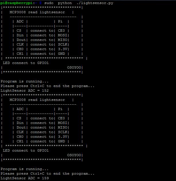
2)Run the program by typing following command:
sudo python ./lightsensor.py
3) Running result
Once run the program, the terminal will show print message as code firstly, then show the lightsensor AD value. when you cover the Photoresistor, the LED brightness will increase, when increase incident light intensity on Photoresistor, the LED brightness will decrease.
Python Sample Code and Explanation comments
import time
import os
import RPi.GPIO as GPIO

# change these as desired - they're the pins connected from the
# SPI port on the ADC to the Cobbler
SPICLK = 11
SPIMISO = 9
SPIMOSI = 10
SPICS = 8
#set BCM_GPIO 18(GPIO1) as LED pin
LEDPIN = 18

analogChannel = 0

#setup function for some setup---custom function
def setup():
    global p
    GPIO.setwarnings(False)
    #set the gpio modes to BCM numbering
    GPIO.setmode(GPIO.BCM)
    # set up the SPI interface pins
    GPIO.setup(SPIMOSI, GPIO.OUT)
    GPIO.setup(SPIMISO, GPIO.IN)
    GPIO.setup(SPICLK, GPIO.OUT)
    GPIO.setup(SPICS, GPIO.OUT)
    #set all LedPin's mode to output,and initial level to HIGH(3.3V)
    GPIO.setup(LEDPIN,GPIO.OUT,initial=GPIO.LOW)
    #set LEDPIN as PWM output,and frequency=100Hz
    p = GPIO.PWM(LEDPIN,100)
    #set p begin with ualue 0
    p.start(0)
    pass


#print message at the begining ---custom function
def print_message():
    print ('|**********************************|')
    print ('|   MCP3008 read lightsensor   |')
    print ('|   -----------------------------  |')
    print ('|    | ADC |           | Pi  |     |')
    print ('|    |-----|-----------|-----|     |')
    print ('|    | CS  | connect to| CE0 |     |')
    print ('|    | Din | connect to| MOSI|     |')
    print ('|    | Dout| connect to| MISO|     |')
    print ('|    | CLK | connect to| SCLK|     |')
    print ('|    | CH0 | connect to| 3.3V|     |')
    print ('|    | CH1 | connect to| GND |     |')
    print ('| ********************************** |')
    print (' LED connect to GPIO1')
    print ('|                            OSOYOO|')
    print ('|**********************************|\n')
    print ('Program is running...')
    print ('Please press Ctrl+C to end the program...')

# read SPI data from MCP3008 chip, 8 possible adc's (0 thru 7)
def readadc(adcnum, clockpin, mosipin, misopin, cspin):
        if ((adcnum > 7) or (adcnum < 0)):
                return -1
        GPIO.output(cspin, True)

        GPIO.output(clockpin, False)  # start clock low
        GPIO.output(cspin, False)     # bring CS low

        commandout = adcnum
        commandout |= 0x18  # start bit + single-ended bit
        commandout <<= 3    # we only need to send 5 bits here
        for i in range(5):
                if (commandout & 0x80):
                        GPIO.output(mosipin, True)
                else:
                        GPIO.output(mosipin, False)
                commandout <<= 1
                GPIO.output(clockpin, True)
                GPIO.output(clockpin, False)

        adcout = 0
        # read in one empty bit, one null bit and 10 ADC bits
        for i in range(12):
                GPIO.output(clockpin, True)
                GPIO.output(clockpin, False)
                adcout <<= 1 if (GPIO.input(misopin)): adcout |= 0x1 GPIO.output(cspin, True) adcout >>= 1       # first bit is 'null' so drop it
        return adcout

#main function
def main():
    while True:
        #print info
        print_message()
        adc = readadc(analogChannel, SPICLK, SPIMOSI, SPIMISO, SPICS)
        print ('LightSensor ADC = %d'%(adc))
        adc=(1023-adc)*100/1023
        p.ChangeDutyCycle(int(adc))
        time.sleep(1)

#define a destroy function for clean up everything after the script finished
def destroy():
    #stop p
    p.stop()
    #turn off led
    GPIO.output(LEDPIN,GPIO.LOW)
    #release resource
    GPIO.cleanup()

#
# if run this script directly ,do:
if __name__ == '__main__':
    setup()
    try:
            main()
    #when 'Ctrl+C' is pressed,child program destroy() will be executed.
    except KeyboardInterrupt:
        destroy()

        adc=(1023-adc)*100/1023
        p.ChangeDutyCycle(int(adc))