
| Buy from US |
 |
Introduction
The OSOYOO Model Y 4-Channel H-Bridge Motor Driver, compatible with 5V MCU, can control up to four DC motors or 2 stepping motors at the same time.
The motor driver board has two PT5126 chip ,two sets of H-Bridge control interfaces (4 PWM input pins and 8 direction control pins). So it can easily control the speed and rotation direction of 4 motors. Compared with the traditional L298N module, which supports only two motors working independently, OSOYOO Model Y module is an idea motor driver for Omni Mecanum wheel cars and other vehicles.
In addition, OSOYOO Model Y has less size and much better efficiency than traditional L298N and L293 H-bridge motor driver. This will give robot and drone motors longer working time .
The chip doesn’t heat in to the rated range, and maximum output 2.8A continuous current. This board includes a built-in low voltage detection circuit and thermal shutdown protection circuit, which is safe and reliable.
The OSOYOO Model Y 4-Channel Motor Driver board comes with four 3.5mm fixing holes, easy for mounting on other devices.This module is suitable for all kinds of DIY production.
The board supports a wide range of input power from 7V to 24V DC. For communication and control, the logic interface is compatible with both 3.3V and 5V systems (such as Arduino, Raspberry Pi, or ESP32).
Specification
- Input Power: 7–24V (Connect to Power Terminals only).
- Logic Level: 3.3V–5V (For I/O pins/Signals).
- High DC output current: Max.=2.8A
- Ultra low RDSON(TOP+BOT): 0.49ΩTYP@25°C, 1A
- Low current consumption when power-down: <0.05μA @25°C
- PWM control, Max. input frequency: 200KHz
- Working Temperature: -40 to +85°C
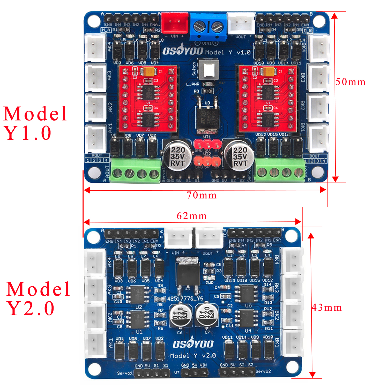
- Model Y1.0 Dimensions: 70 x 50 x18mm(2.8 x 1.9 x 0.7 inch)
- model Y2.0 Dimensions: 43 x 62 mm x12mm(1.7x 2.4 x 0.04 inch)
Model Y dimension
Board Overview
Note:
The VOUT interface is directly connected to the VIN interface, meaning VOUT voltage equals VIN voltage without any voltage regulator chip. Its purpose is to power additional devices. Do not connect the VOUT pin directly to the chip’s power pin to avoid damaging the chip or circuit board.
The onboard servo interface is designed to simplify external MCU control of servos. This driver board does not contain an MCU and cannot directly drive servos. Customers must connect an external driver circuit’s PWM pin to the servo interface’s S pin. Three-wire servos can be connected to the corresponding header pins to simplify wiring and drive the servo.
Model Y V1.0
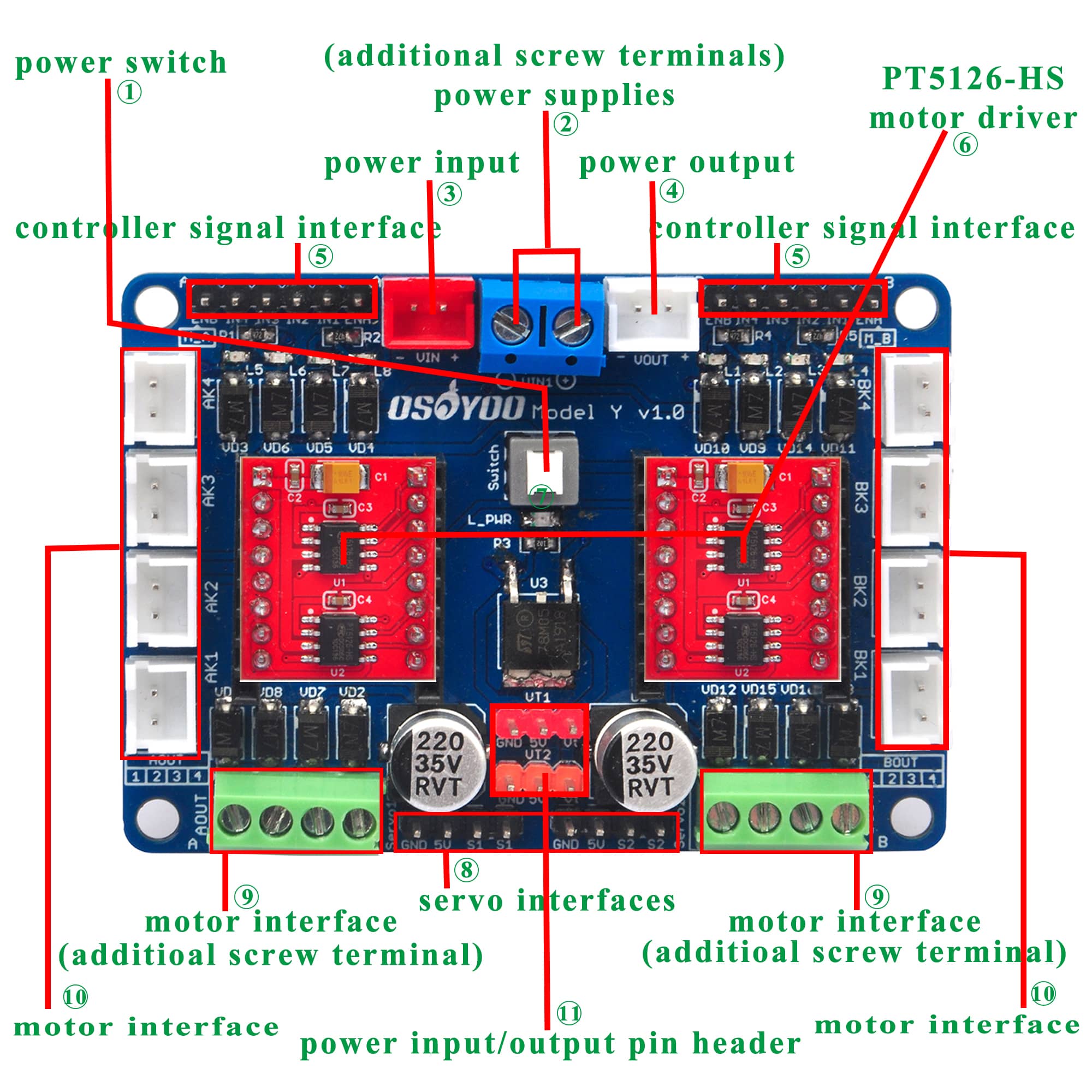
①Power selection switch.
②Additional screw terminals are provided for different power supplies, which can provide a variety of options for powering your project.
③The red XH2.54 anti-reverse terminal is the power input interface.
④Power output interface. Directly connected to VIN without any voltage regulation, it can supply power to other devices.
⑤Controller signal interface, compatible with 5V controllers, we use them to control the rotation direction, rotation speed, start and stop of the motors.
⑥PT5126-HS motor driver. They can drive four DC motors, and each module can individually control two DC motors. If necessary, we can replace them with the most common red TB6612 modules.
⑦Power indicator.
⑧Servo interfaces. In order to better build the robot project, we provide two servo ports, each of which can be connected to a drive pin from the controller and a 3Pin general servo pin.(This interface is designed to simplify wiring and provide 5V power to the servo. This driver board does not contain an MCU and cannot directly drive the servo; it requires an external MCU to supply the PWM servo control signal.)
⑨XH2.54 anti-reverse motor interface. When connecting the motor, just plug it in directly. AK1/AK2 are controlled by the same drive signal, and AK3/AK4 are also controlled by the same signal. The same goes for the four ports on the other side.
⑩Screw terminal motor interface. Provides opportunities for different motors to join this project.
⑪Power input/output pin header. At the same time, an external three-wire voltmeter can be connected to easily check the power supply voltage.
⑫Motor Control Indicator.
Our technical team has consolidated two individual PT5126 boards into a unified board on Model Y v1.0, streamlining the wiring process and enhancing ease of assembly for our customers..
Model Y V2.0
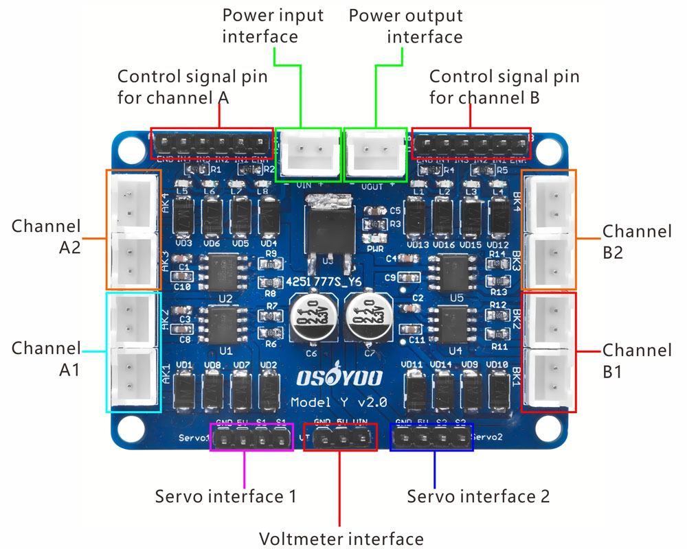
Explanation:
In above picture, you can see 8 sockets which can connect maximum 8 motors.
Socket AK1 and AK2 are synchronous, we call it A1 pair.
Socket AK3 and AK4 are synchronous, we call it A2 pair.
Socket BK1 and BK2 are synchronous, we call it B1 pair.
Socket BK3 and BK4 are synchronous, we call it B2 pair.
A1 Pair motors movement direction is controlled by Channel A control Pin IN1/IN2, Speed is controlled by Channel A ENA
A2 Pair motors movement direction is controlled by Channel A control Pin IN3/IN4, Speed is controlled by Channel A ENB
B1 Pair motors movement direction is controlled by Channel B control Pin IN1/IN2, Speed is controlled by Channel B ENA
B2 Pair motors movement direction is controlled by Channel B control Pin IN3/IN4, Speed is controlled by Channel B ENB
Here is the table of control signals
| Socket |
Movement Direction |
PWM Speed Control Pin |
Direction Pin Value |
| AK1/AK2 |
Forward |
A Channel ENA |
A Channel IN1=1 IN2=0 |
| AK1/AK2 |
Backward |
A Channel ENA |
A Channel IN1=0 IN2=1 |
| AK3/AK4 |
Forward |
A Channel ENB |
A Channel IN3=1 IN4=0 |
| AK3/AK4 |
Backward |
A Channel ENB |
A Channel IN3=0 IN4=1 |
| BK1/BK2 |
Forward |
B Channel ENA |
B Channel IN1=1 IN2=0 |
| BK1/BK2 |
Backward |
B Channel ENA |
B Channel IN1=0 IN2=1 |
| BK3/BK4 |
Forward |
B Channel ENB |
B Channel IN3=1 IN4=0 |
| BK3/BK4 |
Backward |
B Channel ENB |
B Channel IN3=0 IN4=1 |
Dimension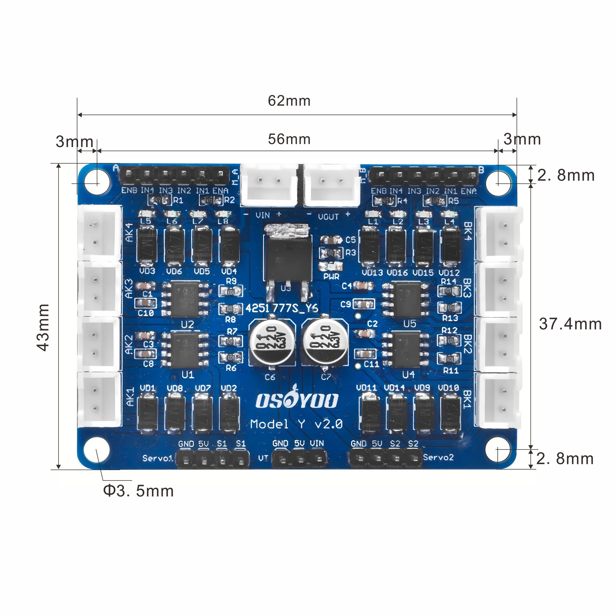 Programming Guide:
1) Sample Motor Connection Graph:
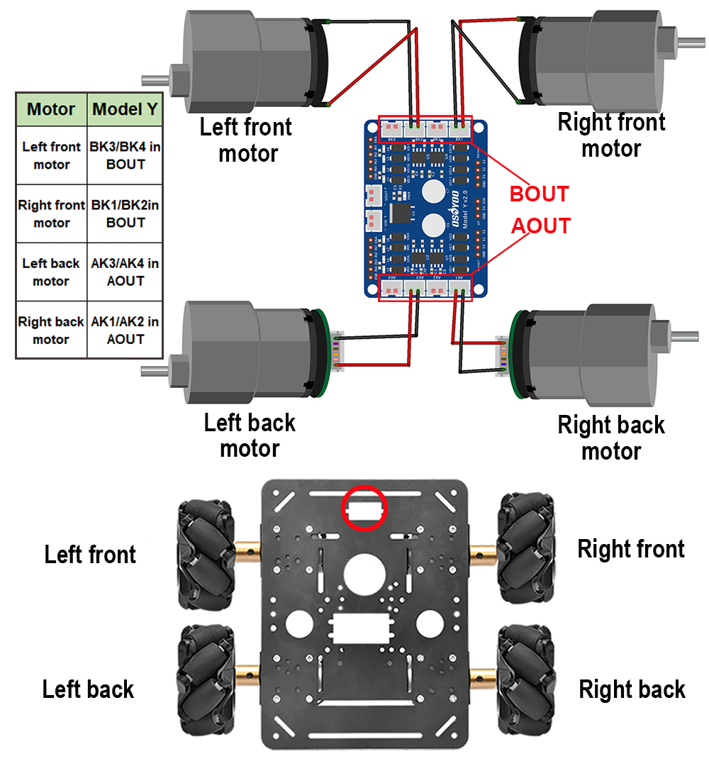
Exmplanation:
Above example uses OSOYOO FlexiRover Frame work +520 DC motor + Mecanum Wheel
It is not necessary to use above hardware, you can use any framework and any DC motor, however OSOYOO DC motors have the XH 2.54 plug which is easier to connect to Model Y 8 output motor sockets. If you want to use your own motor, we suggest you solder a XH2.54 plug in the motor which can firmly insert into socket.
Arduino Wire Connection Example:
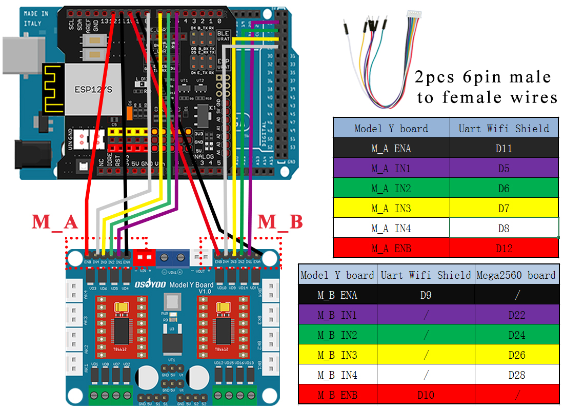
Explanation:
As Model Y H-Bridge needs 12 pin(including 2 PWM) to control 4 independent channels of motors. We strongly recommend to use Arduino MEGA2560 instead of UNO board to control the Model Y module.
Sample Code Code Download https://osoyoo.com/download/model_Y_sample.zip:
#define SPEED               100 //speed is PWM value between 0 to 255
#define TURN_SPEED          100 //speed is PWM value between 0 to 255
#define Speed_BK1_Socket    9   //BK1 Motor Socket Speed controlled by Model-Y Channel-B ENA PWM value
#define Chnl_B_IN1          22  //BK1 Motor Rotate Direction control pin 1 is Channel-B IN1
#define Chnl_B_IN2          24  //BK1 Motor Rotate Direction control pin 2 is Channel-B IN2
#define Chnl_B_IN3          26  //BK3 Motor Rotate Direction control pin 1 is Channel-B IN3
#define Chnl_B_IN4          28  //BK3 Motor Rotate Direction control pin 2 is Channel-B IN4
#define Speed_BK3_Socket    10  //BK3 Motor Socket Speed controlled by Model-Y Channel-B ENB PWM value

#define Speed_AK1_Socket    11  //AK1 Motor Socket Speed controlled by Model-Y Channel-A ENA PWM value
#define Chnl_A_IN1          5   //AK1 Motor Rotate Direction control pin 1 is Channel-A IN1
#define Chnl_A_IN2          6   //AK1 Motor Rotate Direction control pin 2 is Channel-A IN2
#define Chnl_A_IN3          7   //AK3 Motor Rotate Direction control pin 1 is Channel-A IN3
#define Chnl_A_IN4          8   //AK3 Motor Rotate Direction control pin 2 is Channel-A IN4 (K3)
#define Speed_AK3_Socket    12  //AK3 Motor Socket Speed controlled by Model-Y Channel-A  ENB PWM value

void BK1_fwd(int speed)  //front-right wheel forward turn
{
  digitalWrite(Chnl_B_IN1,HIGH);
  digitalWrite(Chnl_B_IN2,LOW);
  analogWrite(Speed_BK1_Socket,speed);
}
void BK1_bck(int speed) // front-right wheel backward turn
{
  digitalWrite(Chnl_B_IN1,LOW);
  digitalWrite(Chnl_B_IN2,HIGH);
  analogWrite(Speed_BK1_Socket,speed);
}
void BK3_fwd(int speed) // front-left wheel forward turn
{
  digitalWrite(Chnl_B_IN3,HIGH);
  digitalWrite(Chnl_B_IN4,LOW);
  analogWrite(Speed_BK3_Socket,speed);
}
void BK3_bck(int speed) // front-left wheel backward turn
{
  digitalWrite(Chnl_B_IN3,LOW);
  digitalWrite(Chnl_B_IN4,HIGH);
  analogWrite(Speed_BK3_Socket,speed);
}

void AK1_fwd(int speed)  //rear-right wheel forward turn
{
  digitalWrite(Chnl_A_IN1, HIGH);
  digitalWrite(Chnl_A_IN2,LOW);
  analogWrite(Speed_AK1_Socket,speed);
}
void AK1_bck(int speed)  //rear-right wheel backward turn
{
  digitalWrite(Chnl_A_IN1, LOW);
  digitalWrite(Chnl_A_IN2,HIGH);
  analogWrite(Speed_AK1_Socket,speed);
}
void AK3_fwd(int speed)  //rear-left wheel forward turn
{
  digitalWrite(Chnl_A_IN3,HIGH);
  digitalWrite(Chnl_A_IN4,LOW);
  analogWrite(Speed_AK3_Socket,speed);
}
void AK3_bck(int speed)    //rear-left wheel backward turn
{
  digitalWrite(Chnl_A_IN3,LOW);
  digitalWrite(Chnl_A_IN4,HIGH);
  analogWrite(Speed_AK3_Socket,speed);
}

void stop_motor()    //Stop
{
  analogWrite(Speed_AK3_Socket,0);
  analogWrite(Speed_AK1_Socket,0);
  analogWrite(Speed_BK3_Socket,0);
  analogWrite(Speed_BK1_Socket,0);
}


//Pins initialize
void init_GPIO()
{
  pinMode(Chnl_A_IN1, OUTPUT);
  pinMode(Chnl_A_IN2, OUTPUT);
  pinMode(Chnl_A_IN3, OUTPUT);
  pinMode(Chnl_A_IN4, OUTPUT);
  pinMode(Speed_AK1_Socket, OUTPUT);
  pinMode(Speed_AK3_Socket, OUTPUT);
  pinMode(Chnl_B_IN1, OUTPUT);
  pinMode(Chnl_B_IN2, OUTPUT);
  pinMode(Chnl_B_IN3, OUTPUT);
  pinMode(Chnl_B_IN4, OUTPUT);
  pinMode(Speed_BK1_Socket, OUTPUT);
  pinMode(Speed_BK3_Socket, OUTPUT);
  stop_motor();
}

void setup()
{
  init_GPIO();
  AK1_fwd(SPEED);
  delay(800);
  stop_motor();
  delay(100);

  AK1_bck(SPEED);
  delay(800);
  stop_motor();
  delay(100);

  AK3_fwd(SPEED);
  delay(800);
  stop_motor();
  delay(100);

  AK3_bck(SPEED);
  delay(800);
  stop_motor();
  delay(100);

  BK1_fwd(SPEED);
  delay(800);
  stop_motor();
  delay(100);

  BK1_bck(SPEED);
  delay(800);
  stop_motor();
  delay(100);

  BK3_fwd(SPEED);
  delay(800);
  stop_motor();
  delay(100);

  BK3_bck(SPEED);
  delay(800);
  stop_motor();

}

void loop(){
}
After you upload the above code into Arduino MEGA2560 board, the motor in AK1, AK3,BK1,BK3 will rotate forward and backward in sequence.


