


| Buy from US |
Buy from UK |
Buy from DE |
Buy from IT |
Buy from FR |
Buy from ES |
ここでご購入を! |
 |
 |
 |
 |
 |
 |
 |
~~~~~~~~~~~~~~~~~~~~~~~~~~~~~~~~~~~~~~~~~~~~~~~~~~~~~~~~~~~~~~~~~~~~~~~~~~~
~~~~~~~~~~~~~~~~~~~~~~~~~~~~~~~~~~~~~~~~~~~~~~~~~~~~~~~~~~~~~~~~~~~~~~~~~~~~~~~~~~~~~~~
縫製電子工作プロジェクト:
~~~~~~~~~~~~~~~~~~~~~~~~~~~~~~~~~~~~~~~~~~~~~~~~~~~~~
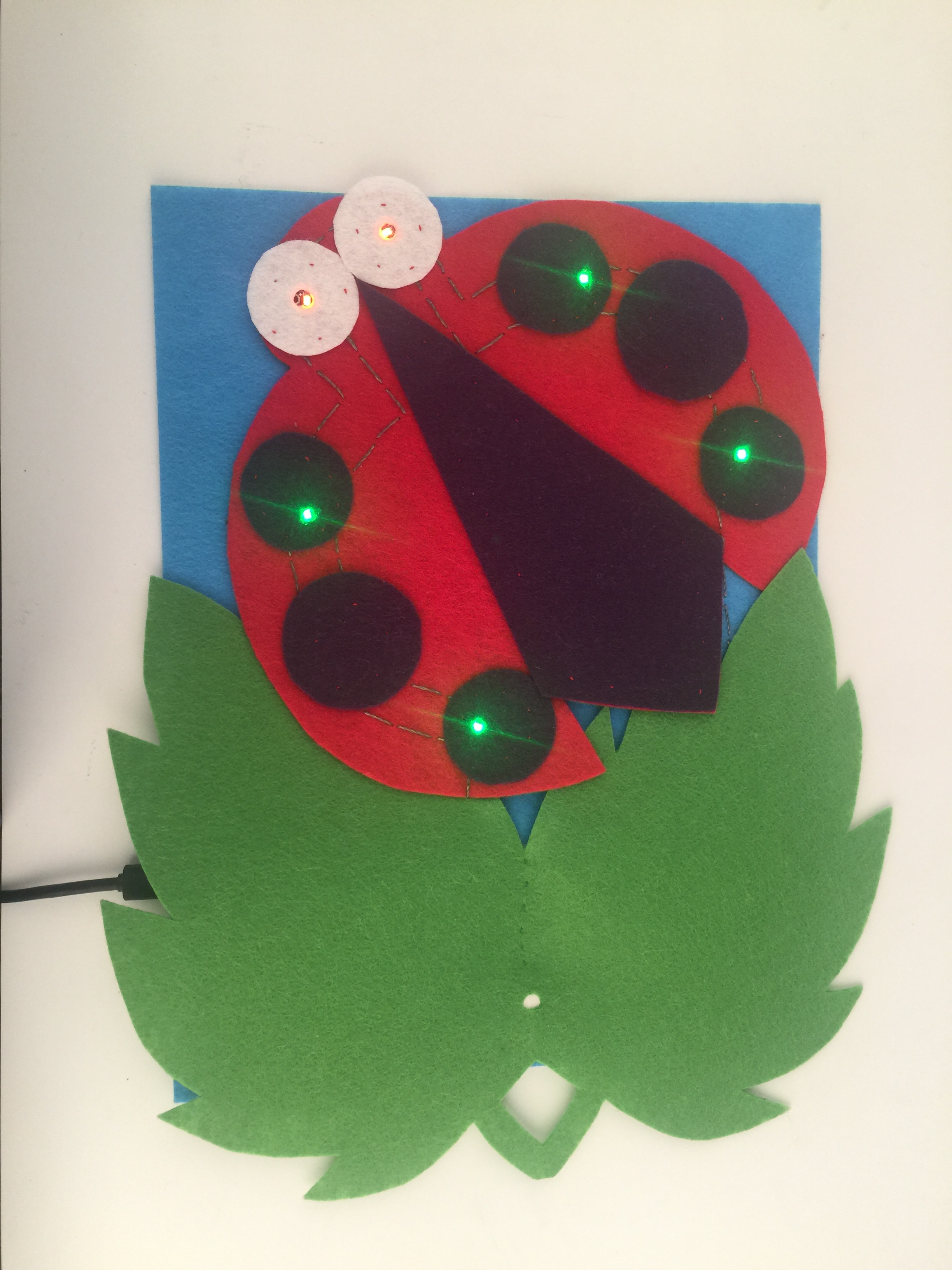
はじめに
このプロジェクトでは、LilyPad USB ボードを使ってLEDを制御します。LilyPad ボードにコードをアップロードすると、プロジェクトはより高度な動作が可能になり、インタラクションを完全に再プログラムできるようになります。LilyPad のコンポーネントをカラフルなフェルトに縫い付け、デザインや装飾を自分好みにカスタマイズしましょう。
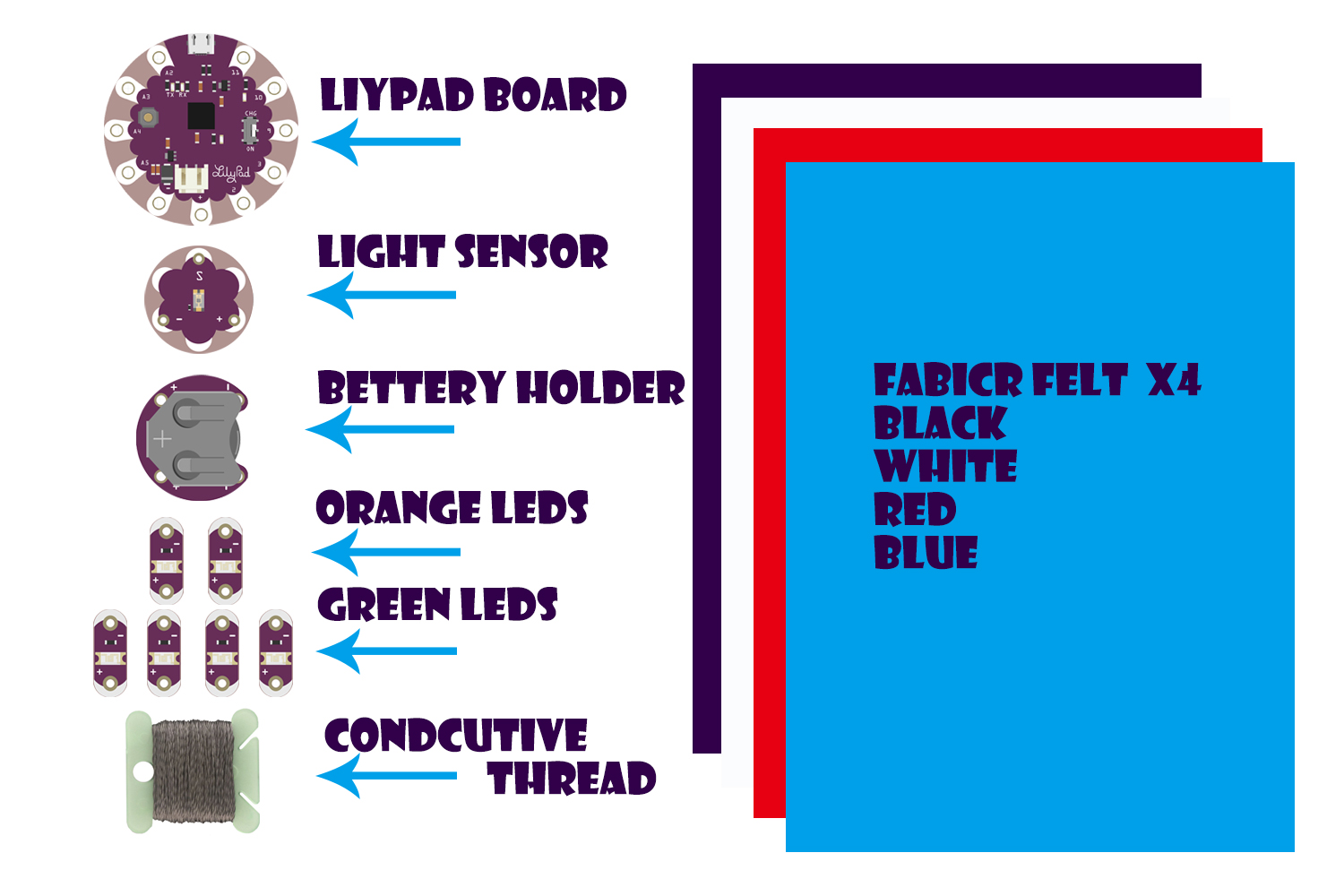
• 1x LilyPad USB ボード
• 1x LilyPad コイン電池ホルダー
• 1x LilyPad 光センサー
• 4x LilyPad LED(緑)
• 2x LilyPad LED(オレンジ)
• 導電糸と縫い針
• テンプレート(1枚)– 印刷用ダウンロードは「プロジェクトを計画する」を参照
• フェルト(23 × 30.5 cm のクラフトフェルト1枚でプロジェクト1個分;装飾には端切れを活用)
• 刺しゅう糸または縫い糸
プロジェクトを計画する
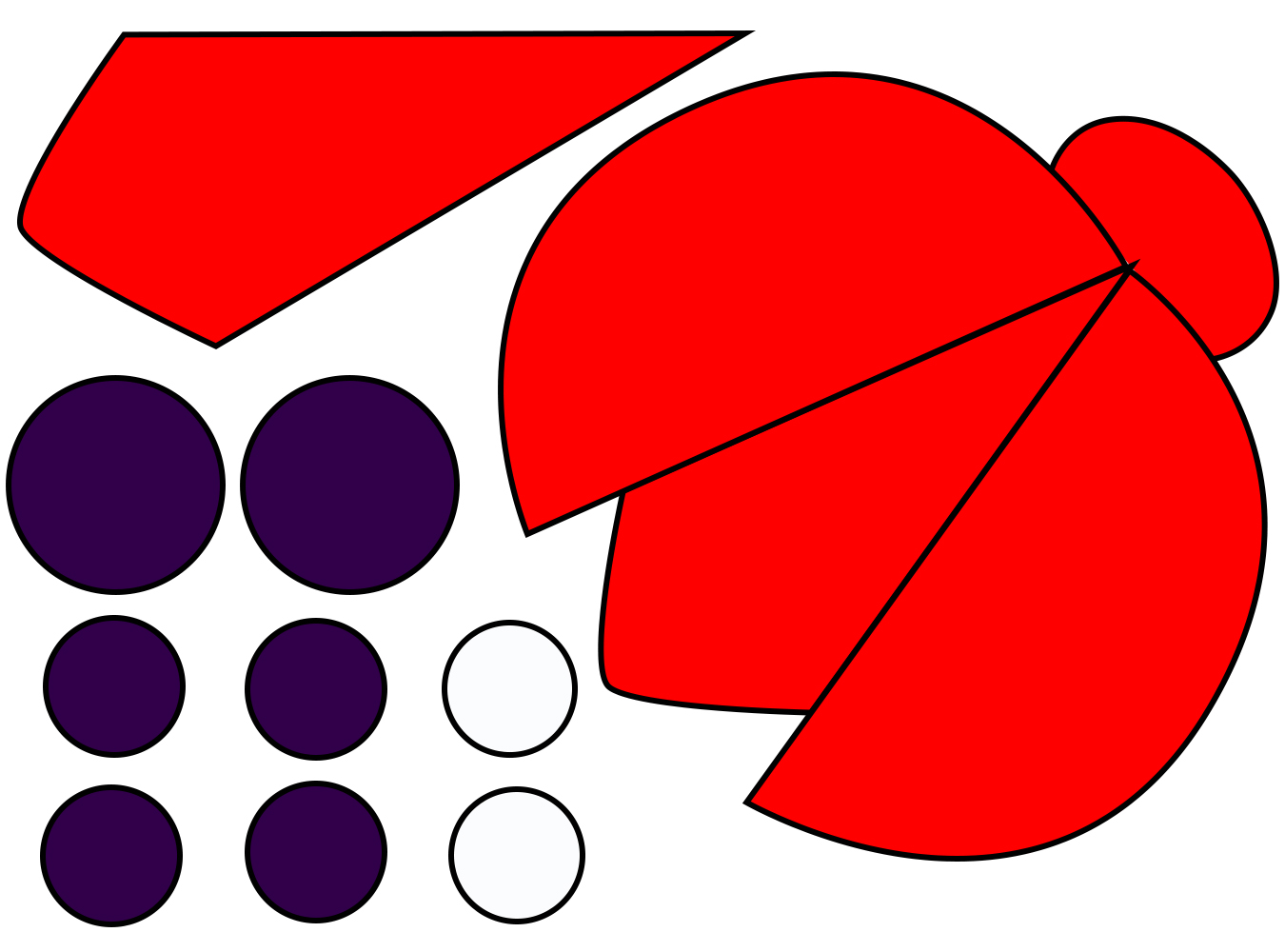
テンプレートの回路図に従うか、紙に自分のレイアウトを設計してください。フェルトにトレースして切り取ります。LilyPad USB ボードを自作のフェルト形状に取り付け、壁に飾ったりプロジェクトに縫い込んだりして完成させます。
ナイトライト・てんとう虫テンプレート
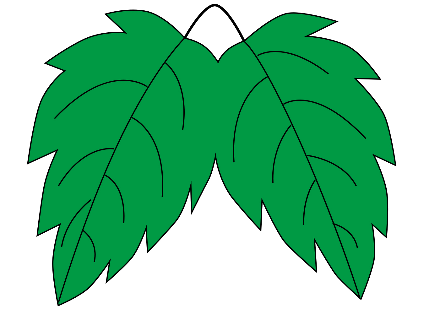
葉っぱテンプレート
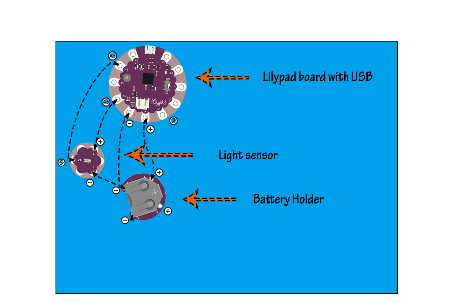
回路を理解する
LilyPad USB は、さまざまなセンサーや接続されたコンポーネントを制御するための情報とコマンドを保存できる小型コンピューターです。LilyPad USB のようなプログラム可能なボードはマイクロコントローラーと呼ばれます。LilyPad には、コードと呼ばれる一連の動作を事前にプログラムする必要があります。
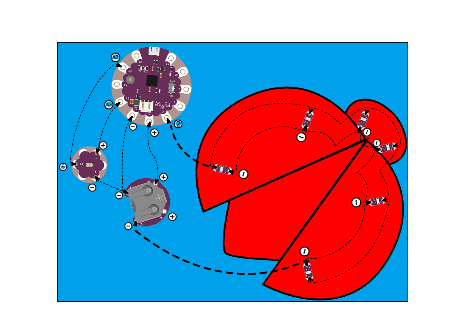
必要な LilyPad パーツは7点です:LilyPad USB ボード、LilyPad コイン電池ホルダー、LED 6個、LilyPad 光センサー。回路図(または自分のデザイン)に従ってパーツをフェルトに配置してください。各パーツを少量の接着剤でしっかりと固定し、接着前に回路図やテンプレートと照らし合わせてパーツの向きを確認してください。

縫い合わせる
ステップ1:
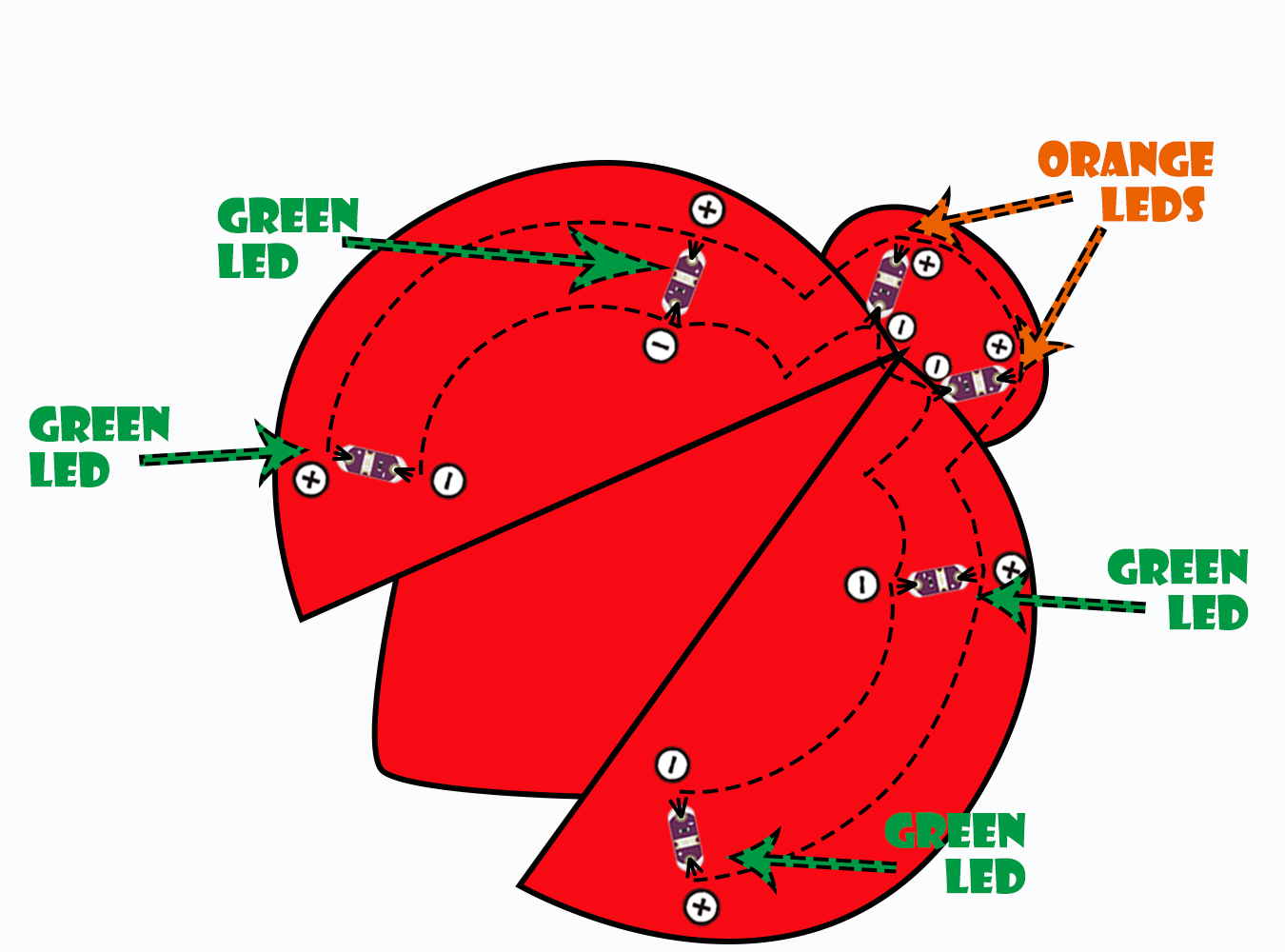
導電糸を長めに切り、針に通してから端に結び目を作ります。最初の接続を縫います:緑色のLED1個のプラスの縫い目タブから始め、6個のLEDをすべてなみ縫いでつなぎ、各プラス(+)の縫い目タブに3回巻きつけます。糸を結んで切ります。3番目と4番目のLEDがオレンジ色であることに注意してください。これらがてんとう虫の目になります。
新しい糸で、マイナス側も同じ手順を繰り返します。6個すべてのLEDのマイナスの縫い目タブを互いにつなぎ、最後に最後の緑色LEDのマイナスの縫い目タブに接続します。仕上げの結び目を作り、余分な糸を切り取ります。
ステップ2:
次に、別の青いフェルトを用意し、そのフェルトの上に LilyPad USB ボードと LilyPad 光センサーを接続します。光センサーには3つの接点があります:センサー(S)、プラス(+)、マイナス(–)。導電糸を使い、LilyPad の A3 タブから光センサーの(S)タブへ、各タブに3回巻きつけながら接続します。LilyPad の A5 タブを光センサーの + タブに接続します。
続いて、LilyPad USB ボードを LilyPad コイン電池ホルダーに接続します。LilyPad USB ボードの(–)タブに3〜4回巻きつけてから、ホルダーの(–)タブを経由して光センサーの(–)タブまで縫い進めます。結んで切ります。新しい糸で、LilyPad USB ボードの(+)タブに3〜4回巻きつけ、ホルダーの(+)タブに接続します。結んで切ります。
ステップ3:
最後に、新しい糸で LilyPad USB ボードのタブ2から始め、縫い目タブに3〜4回巻きつけます。そのまま最後のLEDのプラス側まで縫い進め、3〜4回巻きつけて終わります。
このステップは他のステップより長い糸が必要です。電池ホルダーのマイナス(–)縫い目タブから始め、プロジェクトの外周に沿って縫い進め、反対側にある最後のLEDのマイナスタブに接続します。
ステップ4:
ここをクリックしてコードをダウンロード: Night-Light-Ladybird.ino
LilyPad ボードにコードをアップロードする前に、Arduino IDE をコンピューターにインストールする必要があります。最新バージョンは Arduino のダウンロードページ(https://www.arduino.cc/en/Main/Software)からダウンロードできます。IDE のインストール方法については、Arduino インストールガイド(Windows、Mac、または Linux)を参照してください。
USB データケーブルで LilyPad Arduino USB ボードをコンピューターに接続し(電池が接続された状態で)、スイッチを「CHG」モードにスライドさせると、赤色の LED が点灯し、電池が充電中であることを示します。スイッチが ON の位置にある場合、マイクロコントローラーに電力が供給され、ボードが動作します。
コードをアップロードする前に、いくつかの設定を確認してください。「ボード」が「LilyPad Arduino USB」に設定されていることを確認します。変更するには、ツールメニューを開き、ボードのサブメニューに移動して LilyPad Arduino USB を選択してください。
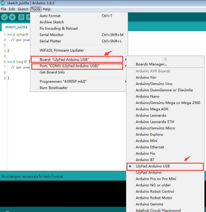
スケッチを開き、右向き矢印ボタンをクリックしてコードをアップロードします。Arduino がコンパイルに数秒、アップロードにもう数秒かかります。
電池を取り付けてテストする
コイン電池をプラス(+)面を上にして LilyPad USB ボードの電池ホルダーに挿入します。光センサーを覆うと、すべての LED が点灯するはずです。点灯したら、電池を取り外して「仕上げ」セクションに進みます。
仕上げ
コードのアップロードについて詳しくはチュートリアル: Arduino スケッチのアップロードをご覧ください。
回路が正常に動作することを確認したら、デザインをカスタマイズしましょう。LED の上に明るい色のフェルトを重ねると、ボードを隠しながら光を柔らかく拡散できます。光センサーをフェルトの飾りで覆う場合は、センサーがふさがれないよう、センサーの上に小さな穴を切り抜いてください。


