In this lesson, we will show you how to make use Internet to monitor remote Light Sensor status.
We will use Osoyoo Mega-IoT Shield to connect Light Sensor(photoresistor), LEDs and MEGA2560 MCU board. OSOYOO Advanced Board for Arduino MEGA2560 can work as a web server. Remote browser can access this web server to shows light sensor real time status.
HARDWARE
OSOYOO MEGA2560 Board x 1
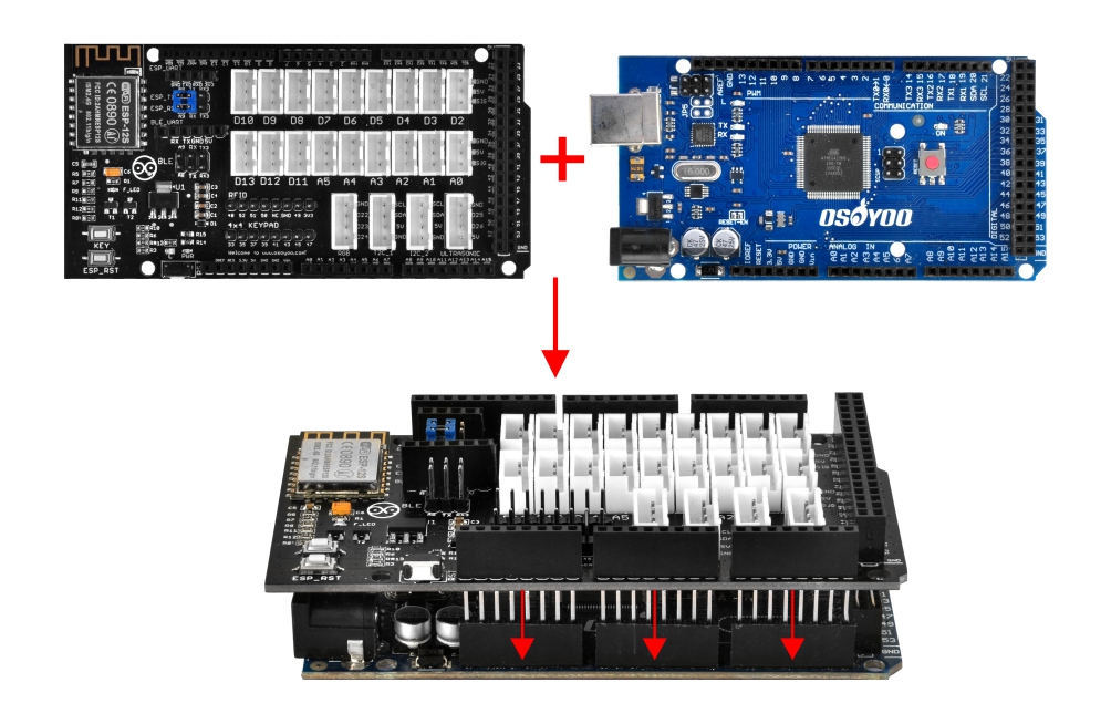
OSOYOO MEGA-IoT Extension Board x 1
Red LED PnP module x 1
Green LED PnP module x 1
Light Sensor(Photoresistor) PnP Module x 1
Buzzer Module x 1
OSOYOO 3-Pin PnP Cable x 4
USB Cable x 1
PC x 1
First, please plug OSOYOO MEGA-IoT Extension Board into MEGA2560 board:
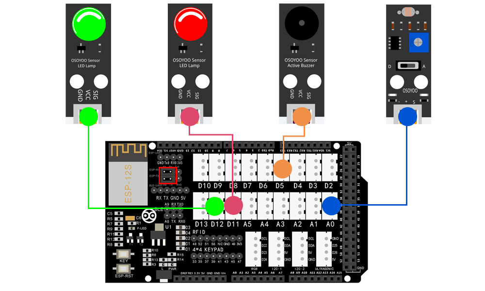
Then connect the modules with the OSOYOO MEGA-IoT Extension Board with four 3-pin PnP cables as below:
(Jumper Cap should connect ESP8266 RX with A8, TX with A9)
Green LED Module – D12
Red LED Module – D11
Buzzer Module – D5
Photoresistor Sensor – A0
Notice: Shut off your battery or Unplug your power adapter when upload sketch code to OSOYOO Advanced Board for Arduino MEGA2560.
Step 1 Install latest IDE (If you have IDE version after 1.1.16, please skip this step)
Download IDE from https://www.arduino.cc/en/software, then install the software.
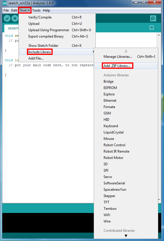
Step 2 WifiEsp Library Installation (if you have installed WifiESP library, please skip this step)
OSOYOO MEGA-IoT extension TX/RX pin to OSOYOO Advanced Board for Arduino MEGA2560 A9/A8 pin by default. So in the sketch code, we need use Software Serial Port to communicate with ESP8266 (set A9 as TX and A8 as RX in softwareserial object).
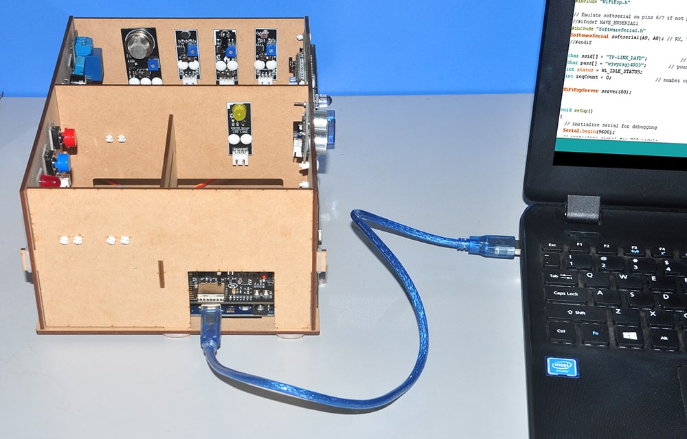
Step 4 After above operations are completed, connect OSOYOO MEGA2560 Board to PC with USB cable.
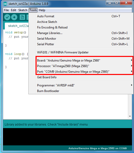
Step 5 IDE: Choose corresponding board type and port type for you project .
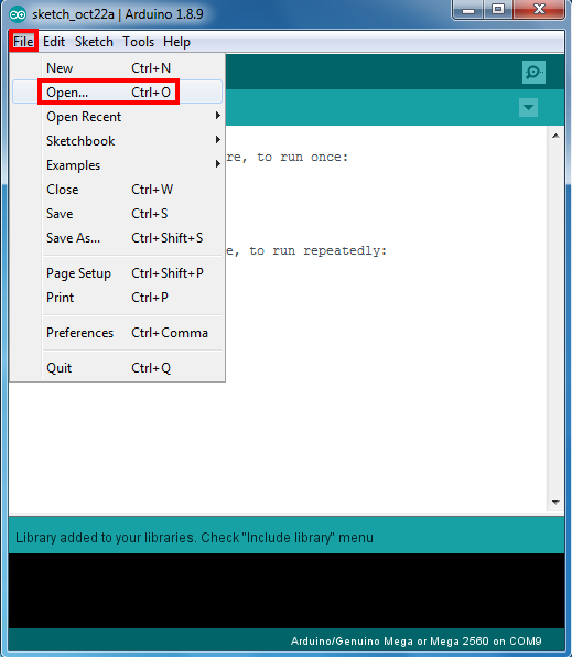
Step 6 IDE: Click file – Open, then choose code “smarthome-lesson12.ino” in the folder, load up the sketch onto your OSOYOO Advanced Board for Arduino MEGA2560.
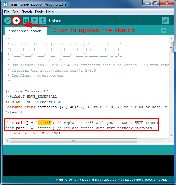
Note: In the sketch, find line 24,25 as following:
char ssid[] = "******"; // your network SSID (name)
char pass[] = "******"; // your network password
please replace the ****** with your correct wifi SSID and password, otherwise your project can not connect to Internet.
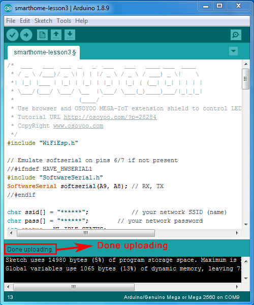
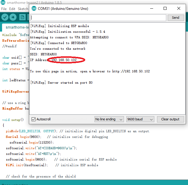
After loading the sketch to OSOYOO Advanced Board for Arduino MEGA2560 , open the serial monitor in the upper-right corner of IDE, you will see following result:
From the serial monitor , you can see the IP address of your MEGA2560 board in the read circle (in above picture, 192.168.50.102).
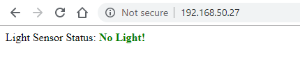
Now use your hand to block all the light over the light sensor, Then use your browser to visit the website http://mega2560-ip-address (in above case, http://192.168.50.102), you will see following result:
Above result means there is no light signal is detected. The Red LED on the D13 pin of MEGA-IoT shield is off and Green LED is ON which shows the same result.
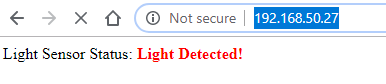
Now expose the light sensor to light source, You will see the Green LED on IoT shield will be off and Red LED will turn ON, buzzer will alarm.
Now check the web browser , after about 2 to 5 seconds, the browser will show following result.
Can you give us some more detail about your problem? Is the code has compiling error or result is wrong? can you copy and paste the error of your Arduino code and result? thanks


Either my Light sensor is bad or the code is not right.
Anyone else have trouble?
Can you give us some more detail about your problem? Is the code has compiling error or result is wrong? can you copy and paste the error of your Arduino code and result? thanks
This is a software problem
change
Serial.println(“Sound detected”);
to
Serial.println(“Light detected”);
It’s around line 84
the English variable names should be cleaned up for a tutorial.
gasStatus should be changed to lightStatus but it works as code.