概述
在前面课程中我们介绍了如何用Raspberry Pi控制单个LED灯,在本课中我们将介绍如何用Raspberry Pi控制红、绿、白、黄8颗LED灯,每种颜色各两颗,实现流水灯的效果。
所需物料
1 * Raspberry Pi
1 * Breadboard
8 * LED
8 * Resistor (200Ω)
Jumper wires
1 * T-Extension Board
1 * 40-Pin Cable
工作原理
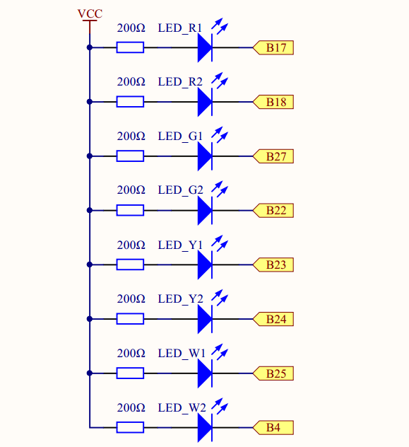
将8颗LED灯正极通过一个200Ω的电阻接到VCC上,LED负极分别连接B17、B18、B22-B25、B4,其中,B代表BCM编码,后面的数字代表BCM编码编号。所以raspberry Pi GPIO口只需要给LED负极一个电平(0V),LED灯就会亮起来,下图为原理图。

实物连接
将8颗LED灯插到面包板上,用跳线接到T型板对应端口上去,具体连接请参考下图。
还没画(o(╯□╰)o)
软件
我们将用两种C语言和Python脚本语言两种方式实现本课要求。如果你有多余显示器,直接把Pi和显示器连接起来;如果没有多余的显示器,可以通过远程登录Pi,具体操作请看考前面的文章。
Raspberry Pi Starter Kit Lesson 1: Get Started with Raspberry Pi
如果你是C语言用户,请参考下面步骤。
1) 在/home/pi目录下新建一个.c源文件
cd ~
sudo nano flow_led.c
cd ~表示进入pi用户主目录;sudo表示以root权限执行命令;nano是一个文本编辑器;flow_led.c是你创建的.c源文件文件名,这个名字可以任意
2) 编码
#include <wiringPi.h>
#include <stdio.h>
首先要包含这个程序需要用到的头文件
//turn on LED --- custom function
void turn_on(int channel){
    digitalWrite(channel,LOW);
}

//turn off LED --- custom function
void turn_off(int channel){
    digitalWrite(channel,HIGH);
}
这是两个自定义函数。将LED所接端口号作为参数传入函数中,实现开关灯操作。这两个函数里面用到了wiringPi库里面的函数,有关wiringPi库的API请访问下面网页查看。
Reference
void setup(){
    int i;
    for(i=0;i<8;i++){
        pinMode(i,OUTPUT);
        digitalWrite(i,HIGH);
    }
}
通过一个for循环将LED的8个端口设置为输出模式,并将每个端口的初始电平设置为高电平(3.3V)。
int main(){
    int i;
    if(wiringPiSetup()==-1){
        printf("setup wiringPi failed!\n");
        printf("please check your setup\n");
        return -1;
    }

    setup();
    printf("\n");
    printf("\n");
    printf("********************************|\n");
    printf("|         Flow LED              |\n");
    printf("|   ------------------------    |\n");
    printf("|                               |\n");
    printf("|   LED_R1 connect to GPIO0     |\n");
    printf("|   LED_R2 connect to GPIO1     |\n");
    printf("|   LED_G1 connect to GPIO2     |\n");
    printf("|   LED_G2 connect to GPIO3     |\n");
    printf("|   LED_Y1 connect to GPIO4     |\n");
    printf("|   LED_Y2 connect to GPIO5     |\n");
    printf("|   LED_W1 connect to GPIO6     |\n");
    printf("|   LED_W2 connect to GPIO7     |\n");
    printf("|                               |\n");
    printf("|                               |\n");
    printf("|                         OSOYOO|\n");
    printf("********************************|\n");

    while(1){
        //turn led from left to right
        printf("|****************************|\n");
        printf("|         ----->>            |\n");
        printf("|    From Left To Right!     |\n");
        printf("|                            |\n");
        printf("|****************************|\n");
        for(i=0;i<8;i++){
            turn_on(i);
            delay(150);
            turn_off(i);
        }
        //turn on from righ to left
        printf("|****************************|\n");
        printf("|         <);
        printf("|     From Right To Left!    |\n");
        printf("|                            |\n");
        printf("|****************************|\n");
        for(i=7;i>=0;i--){
            turn_on(i);
            delay(150);
            turn_off(i);
        }
    }
    return 0;
}
在main函数中调用了自定义函数setup对GPIO进行初始化,然后向终端打印LED与GPIO连接关系。在while循环中8个LED灯先从左到右点亮再从右到左点亮。
完整的程序源代码可以在命令行运行
sudo wget http://osoyoo.com/driver/pi3_start_learning_kit_lesson_5/flow_led.c
3) 编译
运行 下面的命令编译你的c语言程序
gcc -Wall -o flow_led flow_led.c -lwiringPi
其中,gcc是C语言编译器,有关gcc的详细使用请点击这里 ;-o参数用于指定编译后的可执行文件名,这个文件名可以随意命名,这里的flow_led就是编译后的可执行文件名称;-lwiringPi用于指定编译时候依赖的库文件。
4) 运行程序
在运行程序之前,先确定你有没有安装servobalster,可以通过下面的命令查看
ls /etc/init.d/servoblaster
如果输出如图所示,说明你已经安装servoblaster
 如果输出下图所示信息,说明没有安装
 如果你安装了servoblaster,在运行你的程序前,先运行下面的命令
sudo /etc/init.d/servoblaster stop
在命令行运行下面命令,执行程序
sudo ./flow_led
5) 最终结果
程序运行起来后,LED灯从左边到右边依次点亮,再从右边到左边依次点亮。
对于python用户,请按照下面的步骤操作。
若你有多余的显示器,直接用显示器将Pi和显示器连接起来,就可以在Python 3(IDLE)变编写程序了,具体操作请看这里
https://osoyoo.com/2017/06/23/pi3%e5%9f%ba%e7%a1%80%e5%ad%a6%e4%b9%a0%e5%a5%97%e4%bb%b6-lession-2python%e7%82%b9%e4%ba%aeled/
若没有多余显示器,可以通过远程登录访问Pi,如何远程登录,请看这里
Raspberry Pi Starter Kit Lesson 1: Get Started with Raspberry Pi
我们这里以远程登录Pi为例,编写代码
1) 在/home/pi下新建一个flow_led.py文件
cd ~
sudo nano flow_led.py
2) 编码
import RPi.GPIO as GPIO
import time
首先导入程序运行依赖的软件模块
# set 8 pins for 8 leds.
LedPins = [17,18,27,22,23,24,25,4]
这里用一个LedPins(list)列表定义8颗LED所用GPIO端口,其中LedPins是列表名。列表是python的一种数据类型,关于Python列表的更多信息请看这里。从列表中可以看出8颗LED灯分别接到了17,18,27,22,23,24,25,4(均为BCM编码)
#print message at the begining ---custom function
def print_message():
    print ('******************************')
    print ('|            flow leds       |')
    print ('|     ---------------------  |')
    print ('|   LED_R1 connect to GPIO0  |')
    print ('|   LED_R2 connect to GPIO1  |')
    print ('|   LED_G1 connect to GPIO2  |')
    print ('|   LED_G2 connect to GPIO3  |')
    print ('|   LED_Y1 connect to GPIO4  |')
    print ('|   LED_Y2 connect to GPIO5  |')
    print ('|   LED_W1 connect to GPIO6  |')
    print ('|   LED_W2 connect to GPIO7  |')
    print ('|        ----------------    |')
    print ('|                            |')
    print ('|                      OSOYOO|')
    print ('****************************\n')
    print ('Program is running...')
    print ('Please press Ctrl+C to end the program...')
自定义了一个函数向终端打印LED与GPIO的连接关系信息,关于如何定义函数请查看这里 了解更多信息。
#setup function for some setup---custom function
def setup():
    GPIO.setwarnings(False)
    #set the gpio modes to BCM numbering
    GPIO.setmode(GPIO.BCM)
    #set all LedPin's mode to output,and initial level to HIGH(3.3V)
    GPIO.setup(LedPins,GPIO.OUT,initial=GPIO.HIGH)
这里用到RPi.GPIO软件包中的几个函数,其中GPIO.setwarnings(False)函数用于屏蔽掉GPIO口警告信息;GPIO.setmode(GPIO.BCM)函数将GPIO口设置成BCM编码;GPIO.setup(LedPins,GPIO.OUT,initial=GPIO.HIGH)将LedPins列表中的8个GPIO口配置成输出模式,并且初始电平是高电平。关于RPi.GPIO中常用函数使用方法请看这里。
def main():
    #print info
    print_message()
    while True:
        #turn LED on from left to right
        print("***********************")
        print("       ----->>         ")
        print("  From Left To Right!  ")
        print("***********************")
        for pin in LedPins:
            GPIO.output(pin,GPIO.LOW)
            time.sleep(0.2)
            GPIO.output(pin,GPIO.HIGH)
            pass

        #turn LED on from right to left
        print("***********************")
        print("       <)
        print("  From Right To Left!  ")
        print("***********************")
        for pin in reversed(LedPins):
            GPIO.output(pin,GPIO.LOW)
            time.sleep(0.2)
            GPIO.output(pin,GPIO.HIGH)
在main函数中先调用自定义函数print_message向屏幕打印信息,在while循环中嵌套两个for循环分别左至右点亮和从右至左点亮LED。在第二个for循环中用到了一个reversed函数,这是python标准库中的一个函数,关于它的使用请看这里。
在命令行运行下面的命令可以获取完整的Python源码
sudo wget http://osoyoo.com/driver/pi3_start_learning_kit_lesson_5/flow_led.py
2 )运行python程序
在命令行输入一下命令运行你的程序
sudo python ./flow_led.py
3 )最终结果
程序运行起来后,LED灯从左边到右边依次点亮,再从右边到左边依次点亮。


 如果输出下图所示信息,说明没有安装
 如果你安装了servoblaster,在运行你的程序前,先运行下面的命令
Connection (above breadboard to RPI) to the RPI 3 B+ is incorrect. Raspberry 3 B+, the pin 1(Red wire) is NOT on the USB side(showed above picture).
Raspberry 3 B+ PIN 1 on the opposite side of the USB side.
I hope that you will correct it..
Refer GPI pin details –
https://www.raspberrypi.org/documentation/usage/gpio/
https://pinout.xyz/
Thanks!
Sample code cannot be downloaded from raspberry pie. Is there any way?
hi, kimmusu ,
can you tell us which link you can not download the sample code?
Thank you for your quick reply.
It didn’t work yesterday, but I tried again today and it’s a good download.
I’m sorry to have bothered you.