Note: ALL OSOYOO Products for Arduino are Third Party Board which is fully compatitable with Arduino
Authorized Online Retailers:
Content
- Introduction
- Preparations
- About Photoresistor
- Connection
- Upload Sketch
- Program Running Result
- The Expansion Example
Introduction
In this lesson, we will show how to use the photoresistor with an OSOYOO Basic Board , we will monitor the output of a photoresistor, allow the OSOYOO Basic Board to know how light or dark it is. When the light falls below a certain level, the OSOYOO Basic Board turns on an LED.
Preparations
Hardware
- OSOYOO Basic Board (Fully compatible with Arduino UNO rev.3) x 1
- Breadboard x 1
- Photoresistor x 1
- 10k ohm resistor x 1
- 200 ohm resistor x 8
- LED x 8
- M/M jumpers
- USB Cable x 1
- PC x 1
Software
Arduino IDE (version 1.6.4+)
About Photoresistor
Photocells are sensors that allow you to detect light. They are small, inexpensive, low-power, easy to use and don’t wear out. For that reason they often appear in toys, gadgets and appliances. They are often referred to as CdS cells (they are made of Cadmium-Sulfide), light-dependent resistors (LDR), and photoresistors.
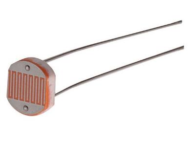
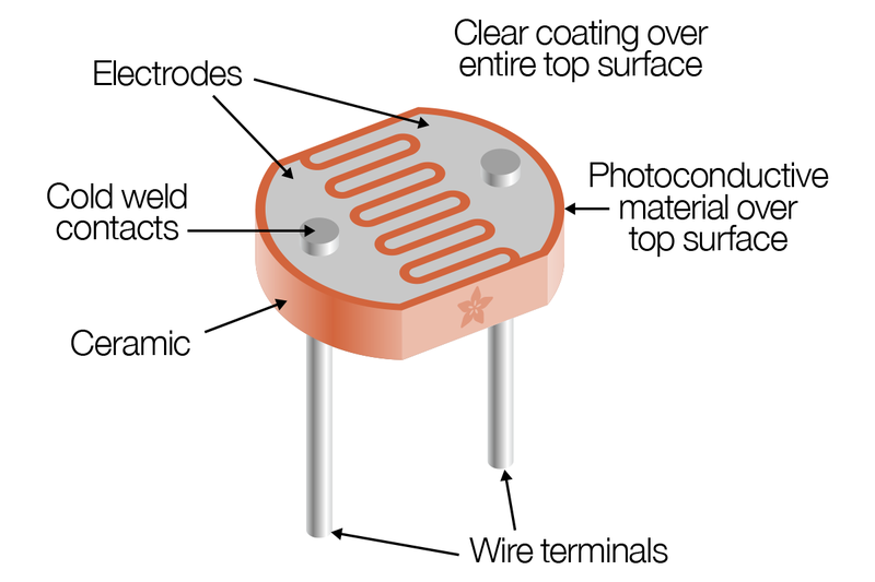
Photocells are basically a resistor that changes its resistive value (in ohms Ω) depending on how much light is shining onto the squiggly face.When it is dark, the resistance of a photoresistor may be as high as a few MΩ. When it is light, however, the resistance of a photoresistor may be as low as a few hundred ohms. They are very low cost, easy to get in many sizes and specifications, but are very innacurate. Each photocell sensor will act a little differently than the other, even if they are from the same batch. The variations can be really large, 50% or higher! For this reason, they shouldn’t be used to try to determine precise light levels in lux or millicandela. Instead, you can expect to only be able to determine basic light changes.
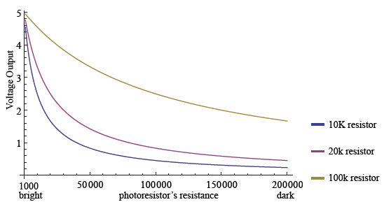
This graph indicates approximately the resistance of the sensor at different light levels:
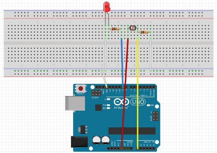
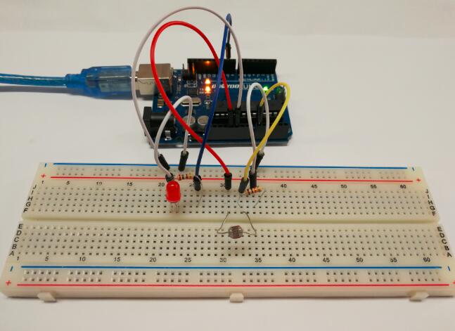
Connection
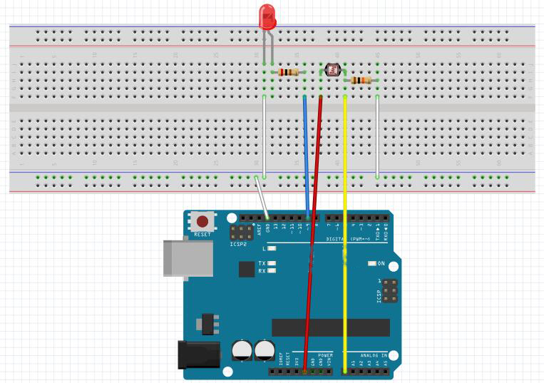
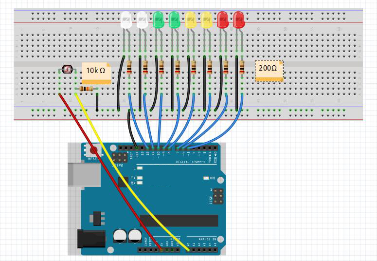
You connect the components as shown in the diagram below. Connect the LED to pin 9 of the OSOYOO Basic Board. The 200 ohm resistor is current limiting resistor. One lead of the photo resistor is connected to 5V, the other to one lead of the 10k ohm resistor. The other lead of the 10k ohm resistor is connected to ground. This forms a voltage divider, whose output is connected to pin A0 of the OSOYOO Basic Board.
As the light impinging on the photoresistor gets stronger, the resistance decreases, and the voltage output of the divider increase. The reverse happens, when the impinging light gets weaker.
Upload Sketch
After above operations are completed, connect the OSOYOO Basic Board to your computer using the USB cable. The green power LED (labelled PWR) should go on.
Code Program
You can download the sketch from this link
In this experiment, we will connect a photoresistor to an OSOYOO Basic Board analog input and read the value with the analogRead() function. Depending on the value the OSOYOO Basic Board reads, the program will then set pin 9 HIGH or LOW to turn on or turn off the LED night lights. The threshold value is 512. When the analog value read is less than 512, the OSOYOO Basic Board will turn the LEDs on. When the analog value it reads is more than 512, the OSOYOO Basic Board will turn the LEDs off.
Compile and upload
Open the Arduino IDE and select corresponding board type and port type for your OSOYOO Basic Board .
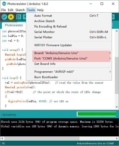
After compile this sketch, simply click the “Upload” button in the environment. Wait a few seconds – you should see the RX and TX leds on the board flashing. If the upload is successful, the message “Done uploading.” will appear in the status bar.
Running Result
If the room is lighted, the LEDs should not light. Try getting them to turn on it by covering the photoresistor with your hand. Remove your hand and observe that they turn off again.
In the same time, open the Serial Monitor and you will get the output data as below :
Note:
When you are using the Serial Monitor, please make sure the baudrate setting is same as your sketch definition.
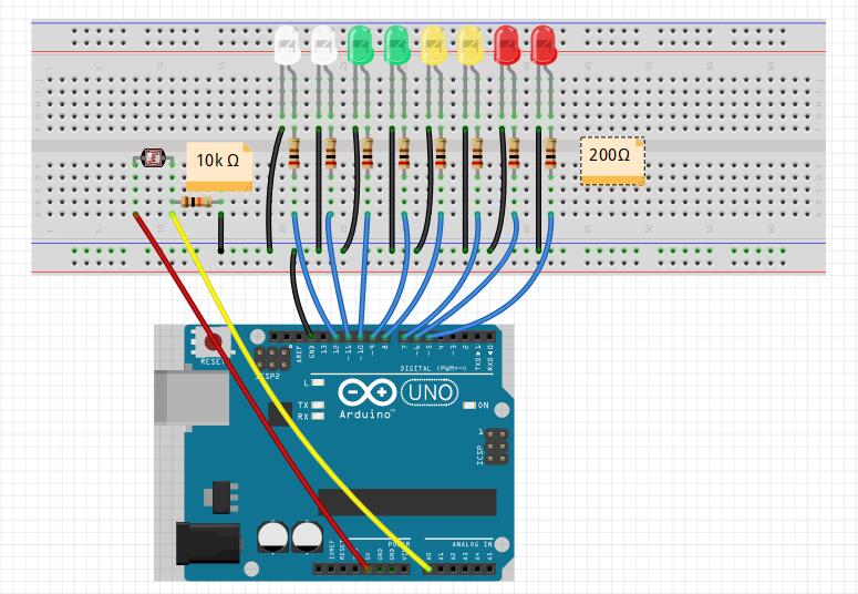
Extended experiment
In this experiment, we will use eight LEDs to indicate light intensity. The higher the light intensity is, the more the LED is lit. When the light intensity is high enough, all the LEDs will be lit. When there is no light, all the LEDs will go out.
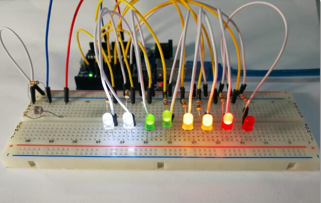
Step 1: Build the circuit
Step 2: Program
You can get the sketch here,
Step 3: Compile the code
Step 4: Upload the sketch to the OSOYOO Basic Board
Now, if you shine the photoresistor with a certain light intensity, you will see several LEDs light up. If you increase the light intensity, you will see more LEDs light up. When you place it in dark environment, all the LEDs will go out.
公式ストアは下記のリンクをクリック
Amazonですぐ購入!