概述
在前面的课程中,我们学习了每一个器件的用法,本课是将是最后一课,在这一课中,我们利用红外遥控器控制继电器、1602、DHT11、蜂鸣器还有光敏电阻等设备。
所需器件
1 * Raspberry Pi 3
1 * Breadboard
1 * IR Receiver(VS1838B)
1 * Infrared Remote Controller
1 *继电器
1 * DHT11
1 * IIC 1602
1 * 蜂鸣器
1 * 光敏电阻
1 * Resistor(10kΩ)
1 *MCP3008
1 * LED
Several jumper wires
1 * T-Extension Board with 40-Pin Cable
实验原理
当遥控器这个红外接收头按按键时候,相应的设备作出相应,例如,按下遥控器上的按键1,开关继电器,按键2开关1602.下表是所用按键对应的设备及设备执行操作。
按键名 被控设备 执行操作
| 按键名 |
被控设备 |
执行操作 |
| 1 |
IIC 1602 |
开启显示 |
| 2 |
IIC 1602 |
关闭显示 |
| 3 |
光敏电阻 |
获取AD值 |
| 4 |
蜂蜜器 |
开/关蜂鸣器 |
| 5 |
DHT11 |
获取温湿度 |
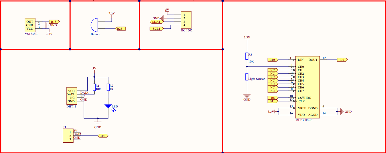
各部分接线图如下

实物连线图
没有画
软件
注意:本课需要依赖于lesson 19中 对LIRC的配置,具体配置请看lesson 19.
1) 下载、解压源代码
cd ~
wget http://osoyoo.com/driver/pi3_start_learning_kit_lesson_20/lesson20-code.tar.gz
tar -xzvf lesson20-code.tar.gz
cd ~/lesson20-code/c-code
2) 编译程序
gcc -Wall -o lesson20 lesson20.c -lwiringPi -llirc_client
3) 运行程序
sudo ./lesson20
如果运行程序报错,运行一下下面命令或者重启pi
sudo /etc/init.d/lirc restart
4) 最终结果
将遥控器对着红外接收头,按下遥控器上的1,1602显示信息;按下2,1602清屏;按下3;获取光敏电阻AD值;按下4,开关蜂鸣器;按下5,获取温湿度。
for python users
1) 下载、解压源代码
cd ~
wget http://osoyoo.com/driver/pi3_start_learning_kit_lesson_20/lesson20-code.tar.gz
tar -xzvf lesson20-code.tar.gz
2) 编辑/etc/lirc/lircrc文件
sudo nano /etc/lirc/lircrc
向lircrc文件中添加如下几行
begin
    prog = irexec
    button = KEY_1
    config = sudo python /home/pi/lesson20-code/python-code/open-1602.py
end
begin
    prog = irexec
    button = KEY_2
    config = sudo python /home/pi/lesson20-code/python-code/close-1602.py
end
begin
    prog = irexec
    button = KEY_3
    config = sudo python /home/pi/lesson20-code/python-code/get-lightsensor.py
end
begin
    prog = irexec
    button = KEY_4
    config = sudo python /home/pi/lesson20-code/python-code/controlbeep.py
end
begin
    prog = irexec
    button = KEY_5
    config = sudo python /home/pi/lesson20-code/python-code/get-tem-hum.py
end
键盘输入Ctrl+X,按输入Y保存退出
3) 运行程序
cd ~/lesson20-code/python-code
irexec
如果运行程序报错,运行一下下面命令或者重启pi
sudo /etc/init.d/lirc restart
4) 最终结果
将遥控器对着红外接收头,按下遥控器上的1,1602显示信息;按下2,1602清屏;按下3;获取光敏电阻AD值;按下4,开关蜂鸣器;按下5,获取温湿度。


There is a wiring error in lesson 20. The signal line from the infrared sensor (OUT pin 3) should connect to the rpi at GPIO18 (physical pin 12) and the buzzer control line (negative side of buzzer) should connect to GPIO23 (physical pin 16).
Thanks for your notice and we have revised the connection graph.