Note: ALL OSOYOO Products for Arduino are Third Party Board which is fully compatitable with Arduino
Content
- Introduction
- Preparations
- About the 4×4 Matrix Keypad
- Examples
- Troubleshooting
Introduction
Keypads are a great way to let users interact with your project. You can use them to navigate menus, enter passwords, and control games and robots.
In this tutorial, I’ll show you how to setup a keypad on the Arduino. First I’ll explain how the Arduino detects key presses, then I’ll show you how to find the pinout of any keypad. As a simple example, I’ll show you how to print out the key presses on the serial monitor and an LCD. Finally, I’ll show you how to activate a 5V relay when a password is entered correctly.
Preparations
Hardware
- Osoyoo Basic Board (Fully compatible with Arduino UNO rev.3) x 1
- 4×4 Matrix Keypad x 1
- I2C 1602 LCD Display x 1
- Relay x 1
- Jumpers
- USB Cable x 1
- PC x 1
Software
- Arduino IDE (version 1.6.4+)
About 4×4 Matrix Keypad

What is keypad?
A keypad is a set of buttons arranged in a block or “pad” which bear digits, symbols or alphabetical letters. Pads mostly containing numbers are called a numeric keypad.
The 4 x 4 matrix keypad usually is used as input in a project. It has 16 keys in total, which means the same input values. It is ultra-thin, easy to interface with any microcontroller and has an adhesive backing for easy mounting for a variety of applications.
Features
- Ultra-thin design
- Adhesive backing
- Excellent price/performance ratio
- Easy interface to any microcontroller
- Example programs provided for the BASIC Stamp 2 and Propeller P8X32A microcontrollers
Specifications
- Maximum Rating: 24 VDC, 30 mA
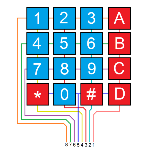
- Interface: 8-pin access to 4×4 matrix
- Operating temperature: 32 to 122 °F (0 to 50°C)
- Dimensions:Keypad, 2.7 x 3.0 in (6.9 x 7.6 cm) Cable: 0.78 x 3.5 in (2.0 x 8.8 cm)
How it Works
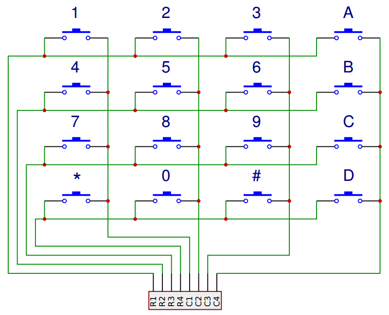
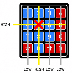
Matrix keypads use a combination of four rows and four columns to provide button states to the host device, typically a microcontroller. Underneath each key is a pushbutton, with one end connected to one row, and the other end connected to one column.
In order for the microcontroller to determine which button is pressed, it first needs to pull each of the four columns (pins 1-4) either low or high one at a time, and then poll the states of the four rows (pins 5-8). Depending on the states of the columns, the microcontroller can tell which button is pressed.
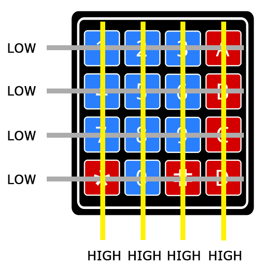
For example, say your program pulls all four columns low and then pulls the 2nd row high. It then reads the input states of each column, and reads pin 3 high. This means that a contact has been made between column 2 and row 2, so button ‘5’ has been pressed.
Applications of 4×4 Matrix Keypad:
- Password Protected Door Security System.
- Wired Remote Controlled Robot.
- Electronic Voting Machine.
- Generating External Interrupt.
- Musical Keypad and many more.
- Multiple DIY Projects.
Examples
Dispaly the pressed button in the Serial Monitor
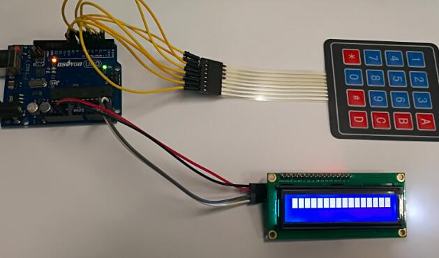
In this project, we will go over how to integrate a keyboard with an Arduino board so that the Arduino can read the keys being pressed by a user. At the end when all is connected properly and programmed, when a key is pressed, it show up at the Serial Monitor on your computer. Whenever you press a key, it shows up on the Serial Monitor.
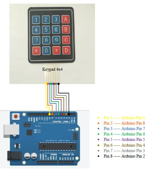
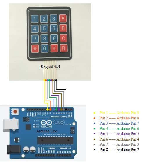
Connection
| Keypad Pin |
Connects to mainboard Pin… |
| 1 |
D9 |
| 2 |
D8 |
| 3 |
D7 |
| 4 |
D6 |
| 5 |
D5 |
| 6 |
D4 |
| 7 |
D3 |
| 8 |
D2 |
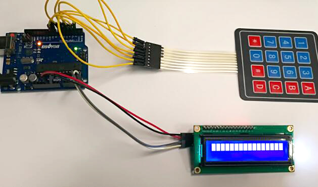
Build the circuit as below:
Code Program
After above operations are completed, connect the Arduino board to your computer using the USB cable. The green power LED (labelled PWR) should go on.Open the Arduino IDE and choose corresponding board type and port type for you project.
Here you visually see all the connections that were written above.Now that we have the physical setup, all we need now is the code. Before you can run this, you have to import the Keypad library and then once you import it, then you can enter it into your program. Once it’s entered into your program, you should see the line #include . If you do not see this, that means that the Keypad library has not been successfully put into your code and it won’t work.
This library is available via the Arduino IDE library manager. If you are using a modern IDE (1.6.2 or above), you can simply use the menu:
Sketch->Include Library->Manage Libraries… Then search for Keypad.
Once found, click on its entry and the install button will appear.
The full instructions for the Keypad library can be found here.
Then load up the following sketch onto your Arduino.
#include <Keypad.h>
const byte ROWS = 4; //four rows
const byte COLS = 4; //four columns
//define the cymbols on the buttons of the keypads
char hexaKeys[ROWS][COLS] = {
  {'1','2','3','A'},
  {'4','5','6','B'},
  {'7','8','9','C'},
  {'*','0','#','D'}
};
byte rowPins[ROWS] = {9, 8, 7, 6}; //connect to the row pinouts of the keypad
byte colPins[COLS] = {5, 4, 3, 2}; //connect to the column pinouts of the keypad

//initialize an instance of class NewKeypad
Keypad customKeypad = Keypad( makeKeymap(hexaKeys), rowPins, colPins, ROWS, COLS);

void setup(){
  Serial.begin(9600);
}

void loop(){
  char customKey = customKeypad.getKey();

  if (customKey){
    Serial.println(customKey);
  }
}
Running Result
A few seconds after the upload finishes, once we press a key on the keypad, it should show up on the serial monitor of the Arduino software.
USING AN LCD WITH THE KEYPAD
Now let’s see how to print the key presses on an LCD. 4X4 keypads use 8 pins . That takes up a lot of pins, so I’m going to use an I2C enabled LCD because it only needs 4 wires to connect to the Arduino.
Connection
Build the circuit as below:
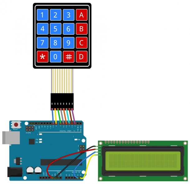
Wiring the I2C 1602 LCD display is pretty straightforward!
| Pin |
Wiring to OSOYOO Basic board |
| SCL |
A5 |
| SDA |
A4 |
| VCC |
5V |
| GND |
GND |
If you’re using other Arduino board rather than the uno, chek out what are their SCL and SDA pins.
- Nano: SDA (A4); SCL(A5)
- MEGA: SDA (20); SCL(21)
- Leonardo: SDA (20); SCL(21)
Code Program
We use an I2C enabled LCD on the Arduino, you’ll need to install the LiquidCrystal I2C library . This library is nice because it includes most of the functions available in the standard LiquidCrystal library. To install it, download the ZIP file, then go to Sketch > Include Library > Add .ZIP Library.
The Wire library is needed to add support for I2C communication. It comes packaged with the Arduino IDE, so there’s no need to install it. But if for some reason it’s not installed on your system, go to Sketch > Include Library > Manage Libraries and search for “wire” to install it.
After above operations are completed, connect the Arduino board to your computer using the USB cable. The green power LED (labelled PWR) should go on.Open the Arduino IDE and choose corresponding board type and port type for you project. Once everything is prepared, upload this code to the Arduino:
#include <Wire.h>
#include <LiquidCrystal_I2C.h>
#include <Keypad.h>

const byte ROWS = 4;
const byte COLS = 4;

char hexaKeys[ROWS][COLS] = {
  {'1', '2', '3', 'A'},
  {'4', '5', '6', 'B'},
  {'7', '8', '9', 'C'},
  {'*', '0', '#', 'D'}
};

byte rowPins[ROWS] = {9, 8, 7, 6};
byte colPins[COLS] = {5, 4, 3, 2};

Keypad customKeypad = Keypad(makeKeymap(hexaKeys), rowPins, colPins, ROWS, COLS);

LiquidCrystal_I2C lcd(0x27, 16, 2);

void setup(){
  lcd.backlight();
  lcd.init();
}

void loop(){
  char customKey = customKeypad.getKey();
  if (customKey){
    lcd.clear();
    lcd.setCursor(0, 0);
    lcd.print(customKey);
  }
}
Each I2C device has an I2C address that it uses to accept commands or send messages. For Uno board, this address usually is 0x27. But sometimes the address might be changed 0x37,0x24 …., So let’s go and look for the one on your device.
Download ic2_scanner sketch zip file , then unzip and load it into Arduino IDE. By opening up the serial monitor in the upright corner, Arduino will scan the address range looking for a reply. Most Arduino board will show 0x27, however it be other number.
Running Result
A few seconds after the upload finishes, once we press a key on the keypad, it should show up on the I2C 1602 LCD display.
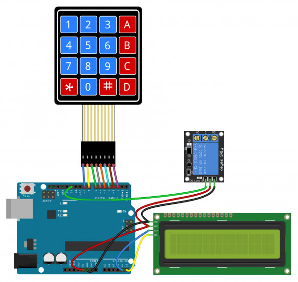
USE A PASSWORD TO ACTIVATE A RELAY
One of the most useful applications of a keypad is to use it for keyed entry. You can set up a password and have the Arduino activate a relay or some other module if the password is correct.
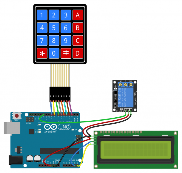
Connection
Build the circuit as below digram:
Code Program
After above operations are completed, connect the Arduino board to your computer using the USB cable. The green power LED (labelled PWR) should go on.Open the Arduino IDE and choose corresponding board type and port type for you project.
The following code will activate a 5V relay when the password is entered correctly, load it to your Arduino board.
#include <Wire.h>
#include <LiquidCrystal_I2C.h>
#include <Keypad.h>

#define Password_Length 8

int signalPin = 12;

char Data[Password_Length];
char Master[Password_Length] = "123A456";
byte data_count = 0, master_count = 0;
bool Pass_is_good;
char customKey;

const byte ROWS = 4;
const byte COLS = 4;

char hexaKeys[ROWS][COLS] = {
  {'1', '2', '3', 'A'},
  {'4', '5', '6', 'B'},
  {'7', '8', '9', 'C'},
  {'*', '0', '#', 'D'}
};

byte rowPins[ROWS] = {9, 8, 7, 6};
byte colPins[COLS] = {5, 4, 3, 2};

Keypad customKeypad = Keypad(makeKeymap(hexaKeys), rowPins, colPins, ROWS, COLS);

LiquidCrystal_I2C lcd(0x27, 16, 2);

void setup(){
  lcd.init();
  lcd.backlight();
  pinMode(signalPin, OUTPUT);
}

void loop(){

  lcd.setCursor(0,0);
  lcd.print("Enter Password:");

  customKey = customKeypad.getKey();
  if (customKey){
    Data[data_count] = customKey;
    lcd.setCursor(data_count,1);
    lcd.print(Data[data_count]);
    data_count++;
    }

  if(data_count == Password_Length-1){
    lcd.clear();

    if(!strcmp(Data, Master)){
      lcd.print("Correct");
      digitalWrite(signalPin, HIGH);
      delay(5000);
      digitalWrite(signalPin, LOW);
      }
    else{
      lcd.print("Incorrect");
      delay(1000);
      }

    lcd.clear();
    clearData();
  }
}

void clearData(){
  while(data_count !=0){
    Data[data_count--] = 0;
  }
  return;
}
You can change the password on line 10 by replacing the 123A456 text with your own password:
char Master[Password_Length] = “123A456”;
The length of the password needs to be set on line 5:
#define Password_Length 8
The password in the example above is only 7 characters long, but the password length is actually one greater than 7 because there is a null character added to the end of the string. For example, if your password is 5 characters long, you would enter 6 for the password length.
The output pin that activates the relay is defined on line 7:
int signalPin = 12;
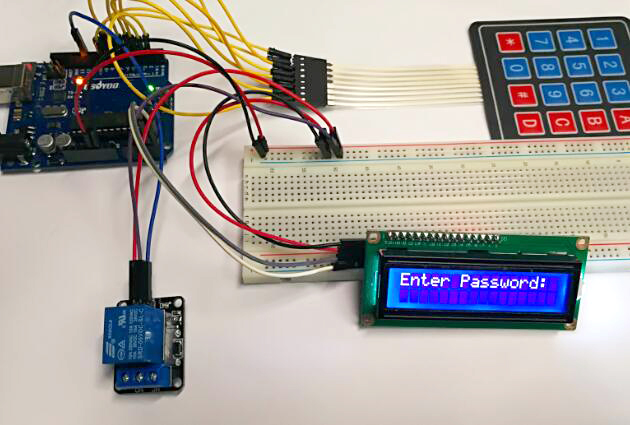
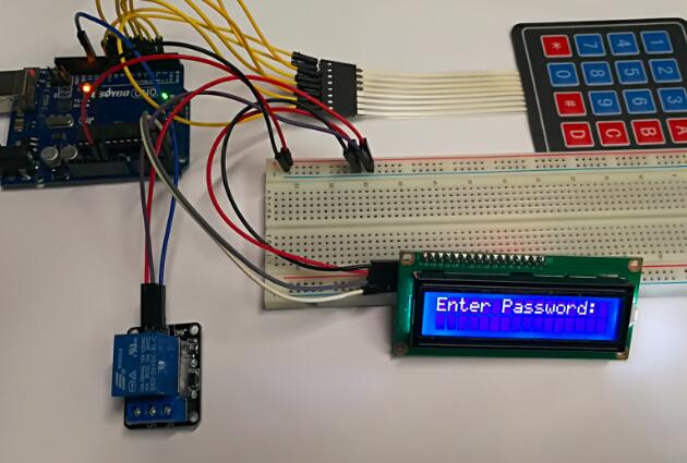
Running Result
A few seconds after the upload finishes, if you enter the correct password, the relay will be activated.

Troubleshooting
1. You can pretty much connect your keypad to any pins you would like. Be careful not to use the serial pins (0 and 1) if you are using them for communication.
2. If key presses seem to take a long time to show up then you are probably using long delay()’s in your code. The same thing can happen if you use too many small delay()s like delay(10).
3. Make sure you understand the pin mappings and have the keypad wired up to match. If you wired the pins incorrectly (and already soldered them in) then you may be able to fix it by redefining the pins and/or keymap to make your keypad work.


i like your project but is it posible to adjust this in my project idia ?
is it easy i need only the kyboard, lcd, and arduino with wifi intrenet conectio.
when I write a number to correspond to a word that I want, and to be sent by e-mail ?
can you help my to that ?