The Ultrasonic Sensor sends out a high-frequency sound pulse and then times how long it takes for the echo of the sound to reflect back. The sensor has 2 openings on its front. One opening transmits ultrasonic waves, the other receives them. In this lesson we will show you how the HC-SR04 Ultrasonic Sensor works and how to use it with the micro bit.
Note: This guide is for the HC-SR04 5v.
Parts Needed You will need the following parts:
1x micro:bit
1x Micro B USB Cable
1x micro:bit Breakout (with Headers)
1x Breadboard
5x Jumper Wires
1x Ultrasonic Sensor Module
About Ultrasonic Sensor HC-SR04
FEATURES OF HC-SR04
Power Supply :+5V DC
Quiescent Current : <2mA
Working Currnt: 15mA
Effectual Angle: <15°
Ranging Distance : 2cm – 400 cm/1″ – 13ft
Resolution : 0.3 cm
Measuring Angle: 30 degree
Trigger Input Pulse width: 10uS
Dimension: 45mm x 20mm x 15mm
WHAT IS ULTRASONIC SENSOR ?
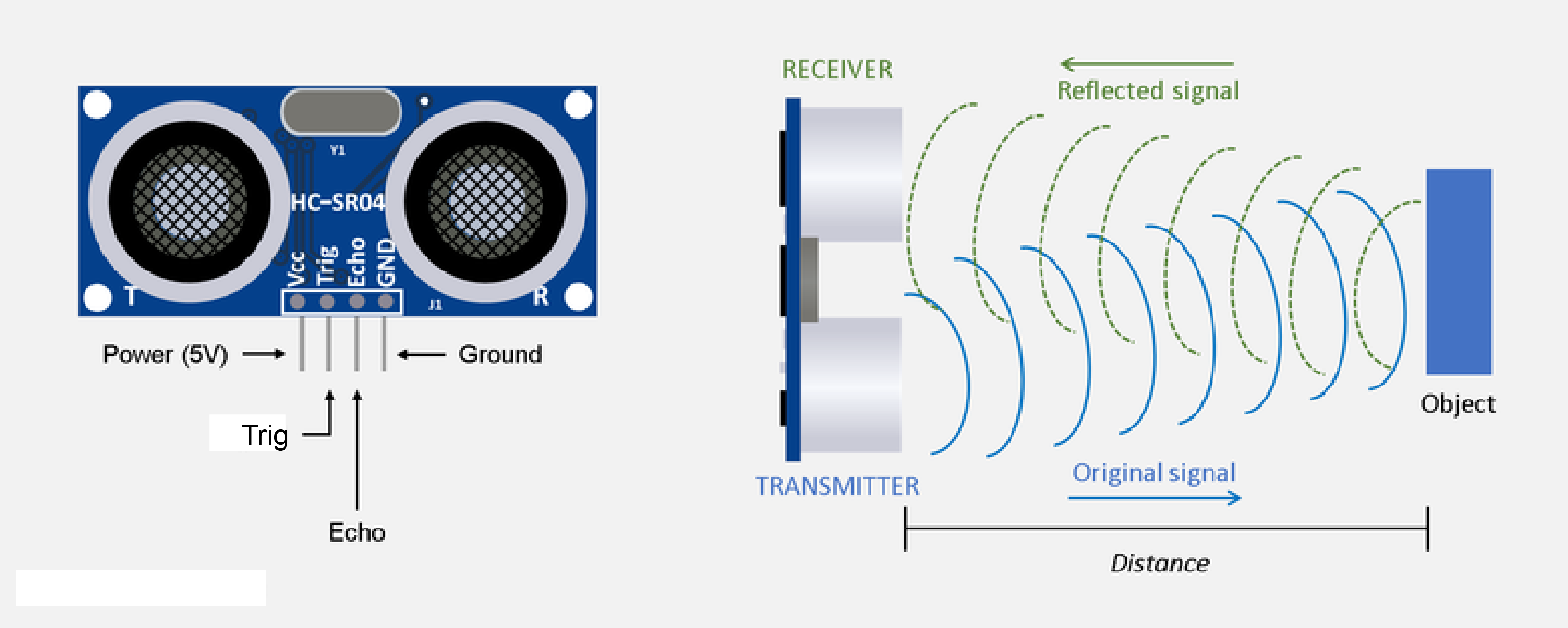
An Ultrasonic sensor is a device that can measure the distance to an object by using sound waves. It measures distance by sending out a sound wave at a specific frequency and listening for that sound wave to bounce back. By recording the elapsed time between the sound wave being generated and the sound wave bouncing back, it is possible to calculate the distance between the sonar sensor and the object.
WHAT IS HC-SR04 ?
The HC-SR04 ultrasonic sensor uses sonar to determine distance to an object like bats do. It offers excellent non-contact range detection with high accuracy and stable readings in an easy-to-use package. From 2cm to 400 cm or 1” to 13 feet. It operation is not affected by sunlight or black material like Sharp rangefinders are (although acoustically soft materials like cloth can be difficult to detect). It comes complete with ultrasonic transmitter and receiver module.On the front of the ultrasonic range finder are two metal cylinders. These are transducers. Transducers convert mechanical forces into electrical signals. In the ultrasonic range finder, there is a transmitting transducer and receiving transducer. The transmitting transducer converts an electrical signal into the ultrasonic pulse, and the receiving transducer converts the reflected ultrasonic pulse back into an electrical signal. If you look at the back of the range finder, you will see an IC behind the transmitting transducer labelled MAX3232. This is the IC that controls the transmitting transducer. Behind the receiving transducer is an IC labelled LM324. This is a quad Op-Amp that amplifies the signal generated by the receiving transducer into a signal that’s strong enough to transmit to the Arduino.
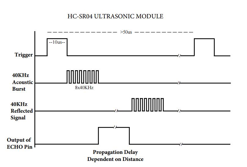
TIMING DIAGRAM
The timing diagram of HC-SR04 is shown. To start measurement, Trig of SR04 must receive a pulse of high (5V) for at least 10us, this will initiate the sensor will transmit out 8 cycle of ultrasonic burst at 40kHz and wait for the reflected ultrasonic burst. When the sensor detected ultrasonic from receiver, it will set the Echo pin to high (5V) and delay for a period (width) which proportion to distance. To obtain the distance, measure the width (Ton) of Echo pin.Time = Width of Echo pulse, in us (micro second)
Distance in centimeters = Time / 58
Distance in inches = Time / 148
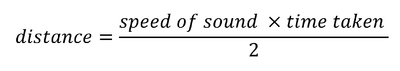
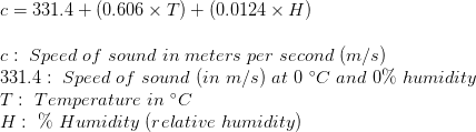
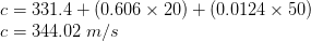
Or you can utilize the speed of sound, since it is known that sound travels through air at about 344 m/s (1129 ft/s), you can take the time for the sound wave to return and multiply it by 344 meters (or 1129 feet) to find the total round-trip distance of the sound wave. Round-trip means that the sound wave traveled 2 times the distance to the object before it was detected by the sensor; it includes the ‘trip’ from the sonar sensor to the object AND the ‘trip’ from the object to the Ultrasonic sensor (after the sound wave bounced off the object). To find the distance to the object, simply divide the round-trip distance in half.The time variable is the time it takes for the ultrasonic pulse to leave the sensor, bounce off the object, and return to the sensor. We actually divide this time in half since we only need to measure the distance to the object, not the distance to the object and back to the sensor. The speed variable is the speed at which sound travels through air. The speed of sound in air changes with temperature and humidity. Therefore, in order to accurately calculate distance, we’ll need to consider the ambient temperature and humidity. The formula for the speed of sound in air with temperature and humidity accounted for is:
For example, at 20 °C and 50% humidity, sound travels at a speed of:
NOTE
It is important to understand that some objects might not be detected by ultrasonic sensors. This is because some objects are shaped or positioned in such a way that the sound wave bounces off the object, but are deflected away from the Ultrasonic sensor. It is also possible for the object to be too small to reflect enough of the sound wave back to the sensor to be detected. Other objects can absorb the sound wave all together (cloth, carpeting, etc), which means that there is no way for the sensor to detect them accurately. These are important factors to consider when designing and programming a robot using an ultrasonic sensor.
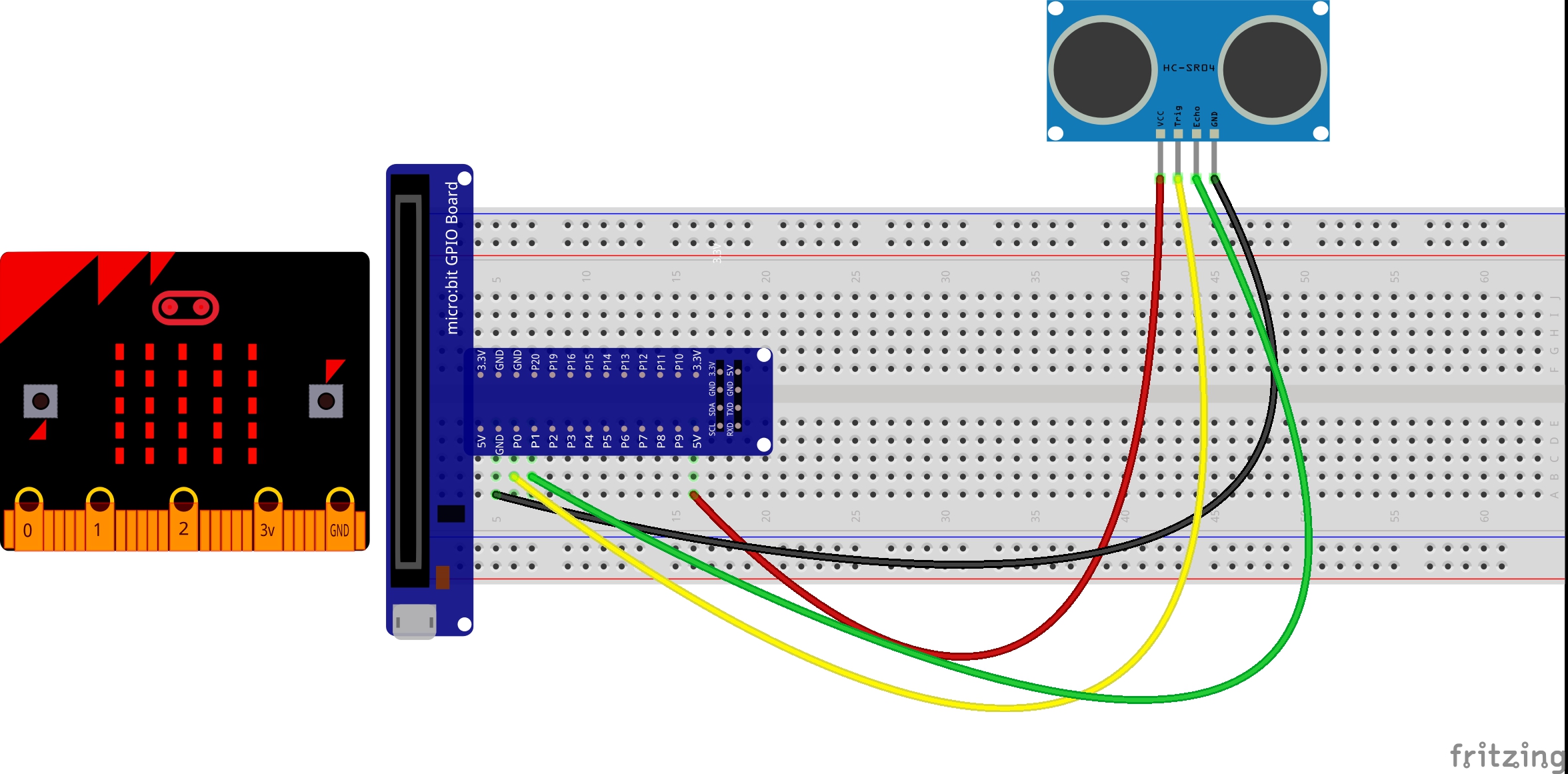
Wiring
You can refer to the column below for the connection between ultrasonic module and micro bit:
Ultrasonic sensor
Micro bit
VCC
5v
GND
GND
Trig
P0
Echo
P1
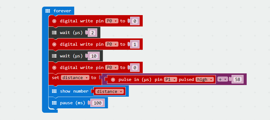
Run Your Script
If you are not familiar to make code, don’t worry. At first, you can enter this link: https://makecode.microbit.org/reference to get the reference of microbit block.
Either copy and paste, or re-create the following code into your own MakeCode editor by clicking the open icon in the upper right-hand corner of the editor window. You can also just download this example by clicking the download button in the lower right-hand corner of the code window.
ICROPYTHON
CAUTION
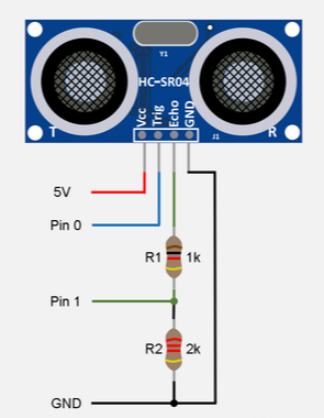
Upon receiving an echo pulse, the ultrasonic sensor will send a “high” signal to Pin 1 of your mcro:bit rated at 5v. The GPIO pin on the micro:bit is rated at 3.3v meaning that, whilst the above solution will work, doing so may damage the GPIO pins on your micro:bit – something we wish to avoid! In order to protect your micro:bit from possible harm, we can lower the voltage being passed to the micro:bit via the echo pin by creating a voltage divider using two resistors.
Creating the voltage divider
A voltage divider consists of two resistors (R1 and R2) connected in a series. In our case, we want to reduce the 5v being returned from the echo pin to a 3.3v – more suitable for our micro:bit.
What resistors you use largely depends on what resistors you have to hand however, without going into too much detail, as a rule of thumb, R2 should be exactly double the value of R1. For example, if we use a 1k ohm resistor for R1 we will need to use a 2k ohm resistor for R2.
Configuration
Our resistors need to be connected in a series. See image right.
Whilst it is possible to achieve the above configuration using crocodile clips, I find it much easier to use a breadboard and jumper wires. See example below.
Result
Now you have already successfully created a set of ultrasonic measuring device. Point the ultrasonic head to the object you would like to test, then you will see the distance between on the LED matrix.


Hi,
May I know why during creating the voltage divider, the echo pin seems to be connected to the ground pin (via a series of resistor)?