Introduction
In this lesson, we will show what is the APDS-9960 RGB and Gesture Sensor and how to hook up it to the Arduino board.
If you do not have specifically a 3.3V Arduino Pro, there are a number of ways to complete the walkthrough. In general, you will need:
- Arduino or other microcontroller — You will need something that is capable of I2C and communicating back to the computer (e.g. serial communications). The microcontroller needs to have a 3.3V I/O voltage or you will have to use a level shifter. We are using the 3.3V Arduino Pro, but the 3.3V Arduino Pro Mini would work as well.
- Level shifting — If you are using a 5V Arduino, like the Uno or RedBoard, you will need to use a level shifter, such as the bi-directional logic level converter.
- Connectors — You will need to interface your microcontroller with the breakout board. Male headers are perfect if you’re using a breadboard. Another option is to use wire to connect the breakout board directly to the microcontroller.
- Soldering tools — After you’ve picked a connector, you will need to solder it to the breakout board. A simple soldering iron and some solder should be all you need.
Preparations
HARDWARE
- 3.3V Arduino Pro x 1
- APDS-9960 RGB and Gesture Sensor x 1
- Jumpers
- USB Cable x 1
- PC x 1
SOFTWARE
- Arduino IDE (version 1.6.4+)
- Arduino library: APDS9960.h
About APDS-9960 RGB and Gesture Sensor
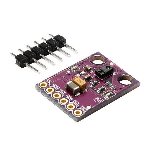
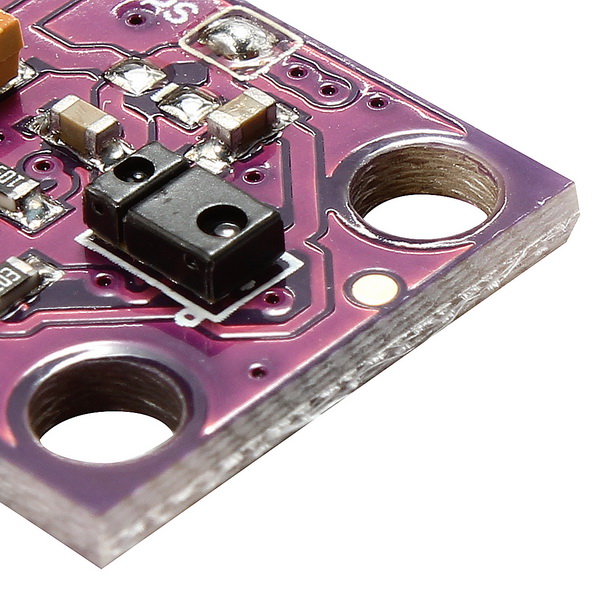
This is the RGB and Gesture Sensor, a small breakout board with a built in APDS-9960 sensor that offers ambient light and color measuring, proximity detection, and touchless gesture sensing. With this RGB and Gesture Sensor you will be able to control a computer, microcontroller, robot, and more with a simple swipe of your hand! This is, in fact, the same sensor that the Samsung Galaxy S5 uses and is probably one of the best gesture sensors on the market for the price.
The APDS-9960 is a serious little piece of hardware with built in UV and IR blocking filters, four separate diodes sensitive to different directions, and an I2C compatible interface. For your convenience we have broken out the following pins: VL (optional power to IR LED), GND (Ground), VCC (power to APDS-9960 sensor), SDA (I2C data), SCL (I2C clock), and INT (interrupt). Each APDS-9960 also has a detection range of 4 to 8 inches (10 to 20 cm).
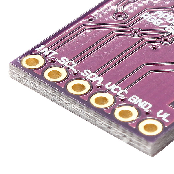
Pin Descriptions
| Pin Label |
Description |
| VL |
Optional power to the IR LED if PS jumper is disconnected. Must be 3.0 – 4.5V |
| GND |
Connect to ground. |
| VCC |
Used to power the APDS-9960 sensor. Must be 2.4 – 3.6V |
| SDA |
I2C data |
| SCL |
I2C clock |
| INT |
External interrupt pin. Active LOW on interrupt event |
Features:
- Model: GY-APDS 9960-3.3
- Using chip: APDS-9960
- Operational Voltage: 3.3V
- Ambient Light & RGB Color Sensing
- Proximity Sensing
- Gesture Detection
- Operating Range: 4-8in (10-20cm)
- I2C Interface (I2C Address: 0x39)
- Size: 20mm * 15.3mm
Recommended Reading
Before getting started with the APDS-9960, there are a few concepts that you should be familiar with. Consider reading some of these tutorials before continuing.
Setting the Jumpers

On the front of the breakout board are 2 solder jumpers:
- PS – This jumper connects the power supplies of the sensor and IR LED (also located on the APDS-9960) together. When the jumper is closed (i.e. connected), you only need to supply power to the VCC pin to power both the sensor and the IR LED. If the jumper is open, you need to provide power to both the VCC (2.4 – 3.6V) and VL (3.0 – 4.5V) pins separately. This jumper is closed by default.
- I2C PU – This is a 3-way solder jumper that is used to connect and disconnect the I2C pullup resistors. By default, this jumper is closed, which means that both SDA and SCL lines have connected pullup resistors on the breakout board. Use some solder wick to open the jumper if you do not need the pullup resistors (e.g. you have pullup resistors that are located on the I2C bus somewhere else).
Hardware Hookup
Add Headers
Solder a row of break away male headers to the 6 headers holes on the board.

Connect the Breakout Board
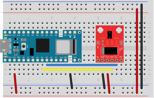
We will be using the Arduino Pro’s regulated 3.3V power and I2C bus with the APDS-9960. Note that we are leaving VL on the breakout board unconnected.
IMPORTANT: You must use 3.3V! If you try to use a 5V power supply you risk damaging the APDS-9960.
Connect the breakout board to the following pins on the Arduino:
| APDS-9960 Breakout Board |
3.3V Arduino Pro |
| GND |
GND |
| VCC |
3.3V |
| SDA |
A4 |
| SCL |
A5 |
NOTE:
- Connect the SCL pin to the I2C clock SCL pin on your Arduino.
On an UNO & ‘328 based Arduino, this is also known as A5, on a Mega it is also known as digital 21 and on a Leonardo/Micro, digital 3
- Connect the SDA pin to the I2C data SDA pin on your Arduino.
On an UNO & ‘328 based Arduino, this is also known as A4, on a Mega it is also known as digital 20 and on a Leonardo/Micro, digital 2
Arduino Library Installation
To use the APDS-9960, you will need some supporting software. If you are using an Arduino, then you are in luck! We created an Arduino library that makes the APDS-9960 easy to use. Click the button below to download the latest version of the APDS-9960 breakout board project, which includes the Arduino library.
DOWNLOAD THE PROJECT FILES!
Follow this guide on installing Arduino libraries to install the files within the APDS9960 directory as an Arduino library.
Gesture Sensing Example
Upload Sketch
After above operations are completed, connect the Arduino board to your computer using the USB cable. The green power LED (labelled PWR) should go on.
CODE PROGRAM
You can copy below code to your Arduino IDE window, then select corresponding board type and port type for your Arduino board.
Running Result
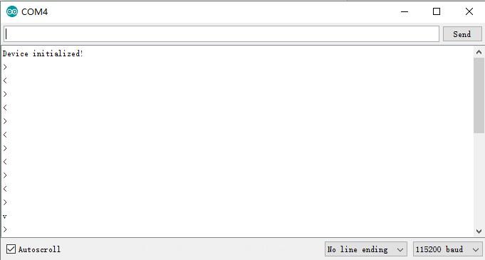
Click the Upload button and wait for the program to finish uploading to the Arduino. Once uploaded to your Adruino, open up the serial monitor at 115200 baud speed.More info on the Serial Terminal can be found here. You should see a messages noting that “Device initialized! ”
Hover your hand 4 to 8 inches (10 to 20 cm) above the sensor but off to one side (i.e. not directly above the sensor). While maintaining the same height, swipe your hand over the sensor (into and then immediately out of range of the sensor). If you move too fast, the sensor will not recognize the gesture.
