Introduction
In this lesson, we will use a potentiometer attached to analog pin A0 and an LED attached to digital pin 9. We use the input from the analog pin to control an LED.
Preparations
HARDWARE
- Osoyoo UNO Board (Fully compatible with Arduino UNO rev.3) x 1
- Breadboard x 1
- Potentiometer(10k) x 1
- 200 ohm resistor x 1
- LED x 1
- M/M jumpers
- USB Cable x 1
- PC x 1
About Potentiometer

A potentiometer is a simple knob that provides a variable resistance, which we can read into the Arduino board as an analog value.In this example, that value controls the rate at which an LED blinks.
So what’s the difference between an analog value and a digital one? Simply put, digital means on/off, high/low level with just two states, i.e. either 0 or 1. But the data state of analog signals is linear, for example, from 1 to 1000; the signal value changes over time instead of indicating an exact number. Analog signals include those of light intensity, humidity, temperature, and so on.
In this lesson, a potentiometer, or pot, is used to change the current in the circuit so the blink rate of the LED will change accordingly. And since the pot is an analog device, the current change is smooth, thus the blink rate will gradually get faster or slower instead of going through an obvious stepwise process.
What we mean by PWM here is the digitalization of analog signals, which is a process of approaching analog signals. Since the potentiometer inputs analog signals, it should be connected to analog ports, i.e. A0-A5, instead of digital ports.
| Electronic symbol |
 (International) (International)
 (US/Canada) (US/Canada) |
Connection
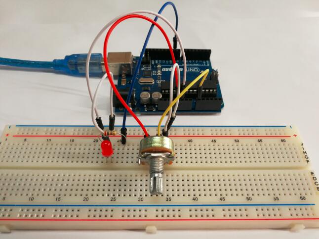
Build the circuit as below:
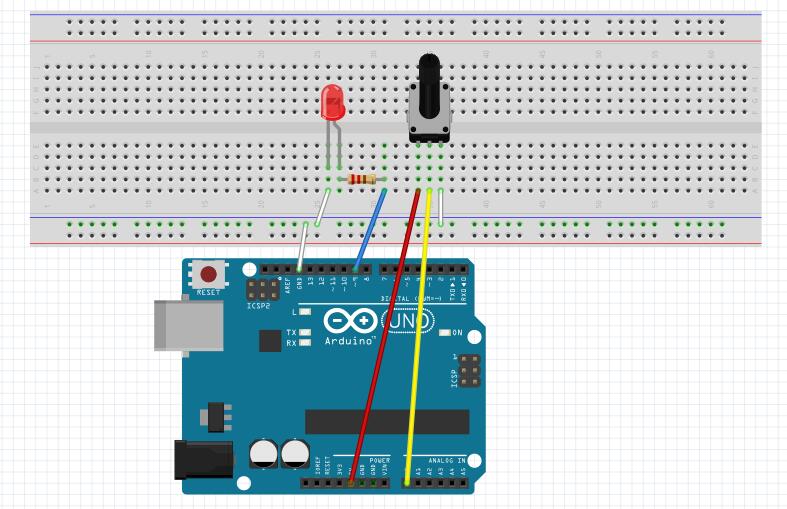
We connect three wires to the Arduino board. The first goes to ground from one of the outer pins of the potentiometer. The second goes from 5 volts to the other outer pin of the potentiometer. The third goes from analog input 0 to the middle pin of the potentiometer.
Code Program
Connect the Arduino board to your computer using the USB cable. The green power LED (labelled PWR) should go on. In this example, let’s see how to change the luminance of an LED by a potentiometer , and receive thedata of the potentiometer in Serial Monitor to see its value change.
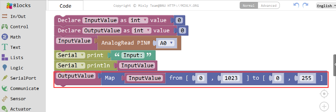
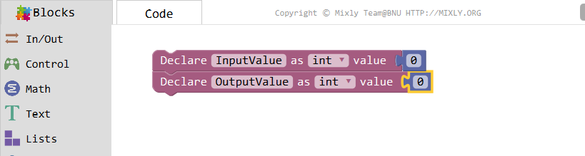
Declare two integer variables: Inputvalue, Output Value.
The potentiometer’s value wiige with its knobead by the analog pin A0 to InputValue.
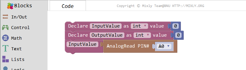
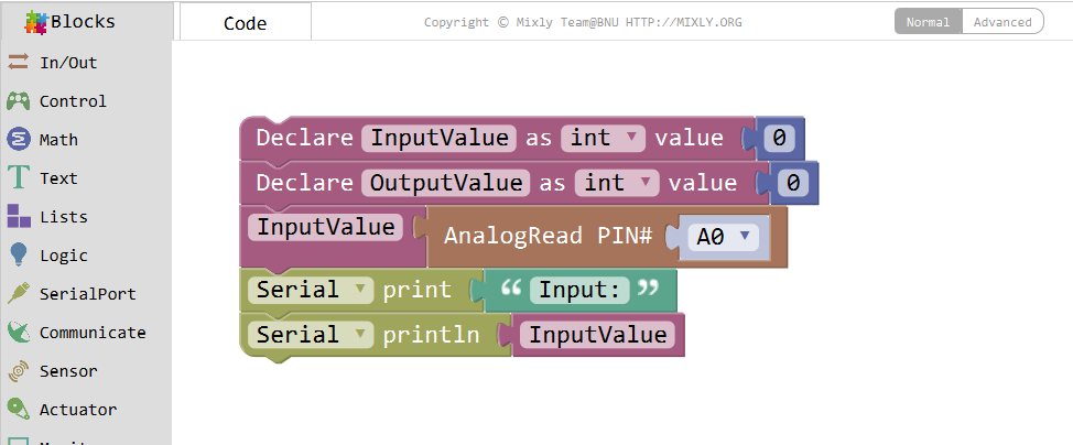
Set the following blocks to print”Input:” and the InputValue, then jump to the next line automatically.
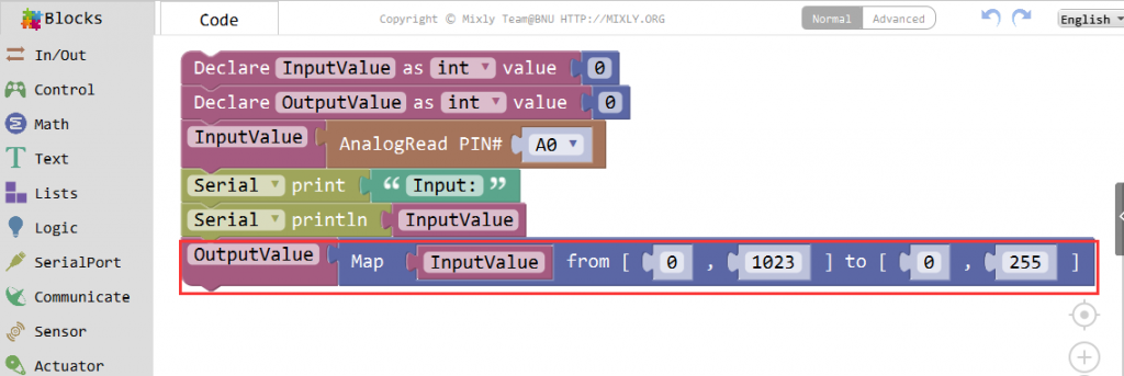
Convert the value from 0-1023 proportionally to that in the range 0-255, and assign it to OutputValue. Find the Map block in Math category.
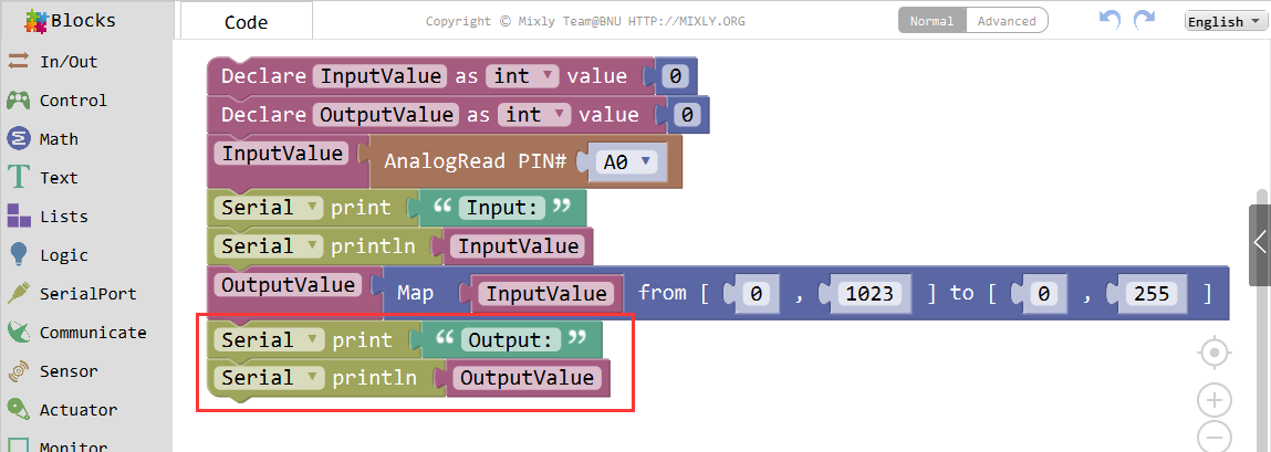
Set the following blocks to print”Output”and the OutputValue similarly.

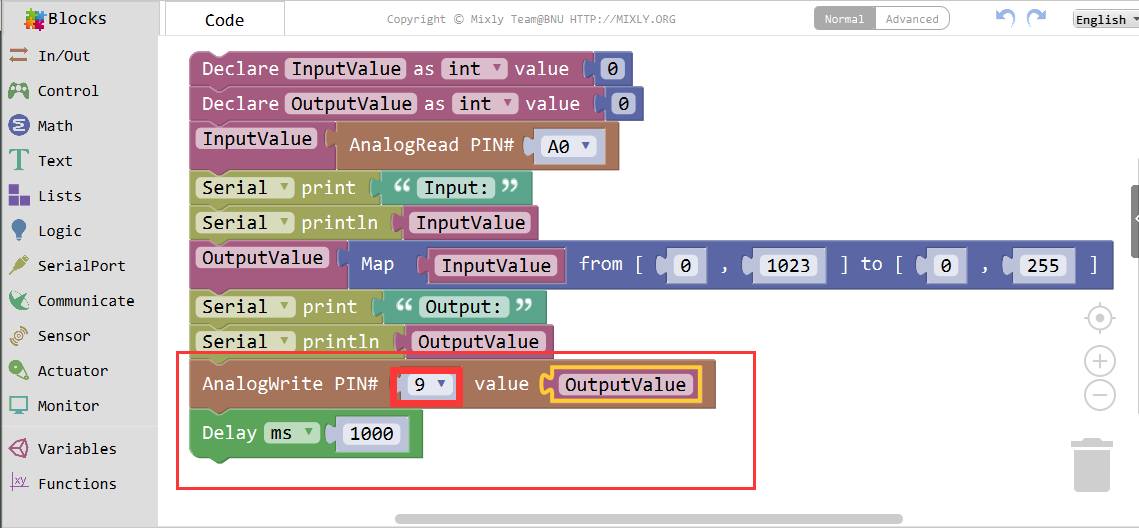
Set pin 9 as output, and add a Delay for 1s.

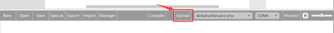
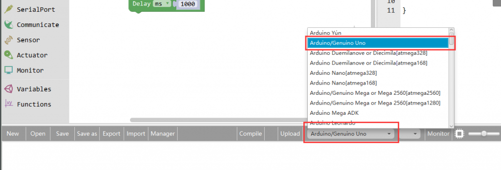
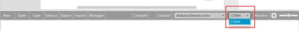
Click Save aftogramming is done. Select the board type and serial port before uploading. For instause a Uno board, just select Arduino/Genuino Uno: if you use a Mega2560, select Arduino/Genuino Mega or Mega2560.
Select the serial device of the Arduino board from the COM menu. This is likely to be COM3 or higher (COM1 and COM2 are usually reserved for hardware serial ports). To find out, you can disconnect your Arduino board and re-open the menu; the entry that disappears should be the Arduino board. Reconnect the board and select that serial port.
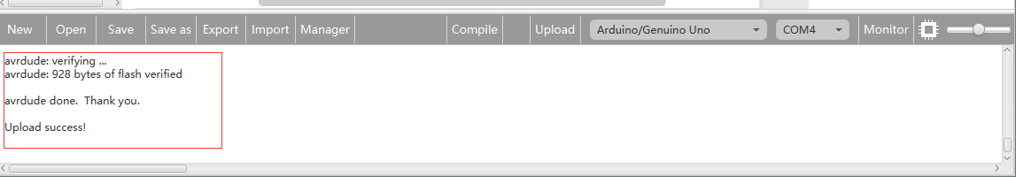
Next,upload the code. If the uploading fails, check and correct the code according to the prompts

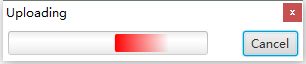
Finally, the staus will change to ‘Upload success!’.

Runnig Result
As you see, the potentiometer is connected to pin A0 of the Osoyoo Uno board, which can measure voltages from 0V to 5V. The corresponding returned value is from 0 to 1024. The measurement accuracy for voltage change is relatively high.
A few seconds after the upload finishes,rotate the shaft of the potentiometer and you should see the luminance of the LED change.:
If you want to check the corresponding value changes, open the Serial Monitor and the data in the window will change with your spinning of the potentiometer knob.