Authorized Retailers
| Buy from US |
Buy from UK |
Buy from DE |
Buy from IT |
Buy from FR |
Buy from ES |
ここでご購入を! |
 |
 |
 |
 |
 |
 |
 |
Introduction
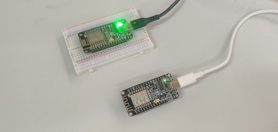
In this lesson, we will demonstrate how to use the Arduino IDE to write code examples that allow two NodeMCUs to communicate using the UDP protocol.
Preparation
Hardware:
Software:
Connection
Connect each of the two NodeMCU modules to the computer via USB cable.
Upload Sketch
Open the Arduino IDE(Version1.6.4+), open the following two codes separately and upload them to the corresponding two NodeMCUs after editing them as described below.
Edit the code to fit your own WiFi settings as following operations:
1)Hotspot Configration:
// Replace with your network credentials
const char* ssid = “Your_WiFi_SSID”; //Replace with your SSID
const char* password = “Your_WiFi_Password”; //Replace with your Password
Find above code line,put your own ssid and password on there.
2)IPddress & Port Settings
After completing the previous steps, we can upload the code to the NodeMCU and then turn on the serial monitor, and if the networking is successful, we can get the corresponding IP address.
If we get the IP of NodeMCU-2 is 192, 168, 0, 17, we will change the code to be uploaded to NodeMCU-1 as the following:
// Destination IP and Port
IPAddress destIP(192, 168, 0, 17); // Replace with the IP of NodeMCU2
unsigned int destPort = 8888; // Replace with the port number of NodeMCU2
If we get the IP of NodeMCU-1 is 192, 168, 0, 15, we will change the code to be uploaded to NodeMCU-1 as the following:
// Destination IP and Port
IPAddress destIP(192, 168, 0, 15); // Replace with the IP of NodeMCU1
unsigned int destPort = 8888; // Replace with the port number of NodeMCU1
We use the “8888” local port here, you can change it to your own local port, change the IP address to the one you got in the previous steps, then, load the modified codes to the NodeMCU again.
3)Boad & COM Port Settings
After do that,choose the coresponding board type and port type as below,then upload the sketch to the NodeMCU.
- Board:”NodeMCU 1.0(ESP-12E Module)”
- CPU Frequency:”80MHz”
- Flash Size:”4M (3M SPIFFS)”
- Upload Speed:”115200″
- Port: Choose your own Serial Port for your NodeMCU
Running Result
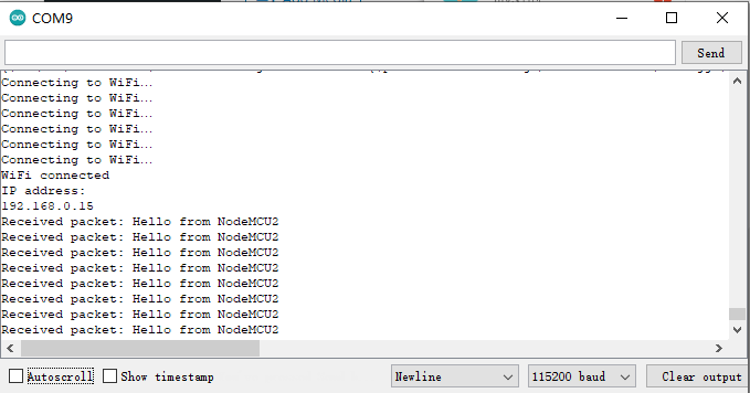
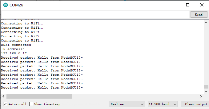
Upload both codes on both NodeMCUs separately and make sure they are both connected to the same WiFi network. You should then be able to see the communication between them in the serial monitor.
Open the Serial Monitor of NodeMCU-1, and you will see as below:
Open the Serial Monitor of NodeMCU-2, and you will see as below:
NOTE:
We need to note that ESP8266 is a 2.4G WiFi device, please access to 2.4G network, if you access to a 5G router network, there will be a prompt that the network connection is not successful.
Part details
SKU: DKRK100700


