Note: ALL OSOYOO Products for Arduino are Third Party Board which is fully compatitable with Arduino
RFID – Radio Frequency Identification, has become part of everyday life, for example, with electronic vehicle tolling, door access control, public transport fare systems and so on.
RFID normally has two components: RFID key and RFID reader(sensor). In this project, we will use RFID reader to get the hidden ID from the key.
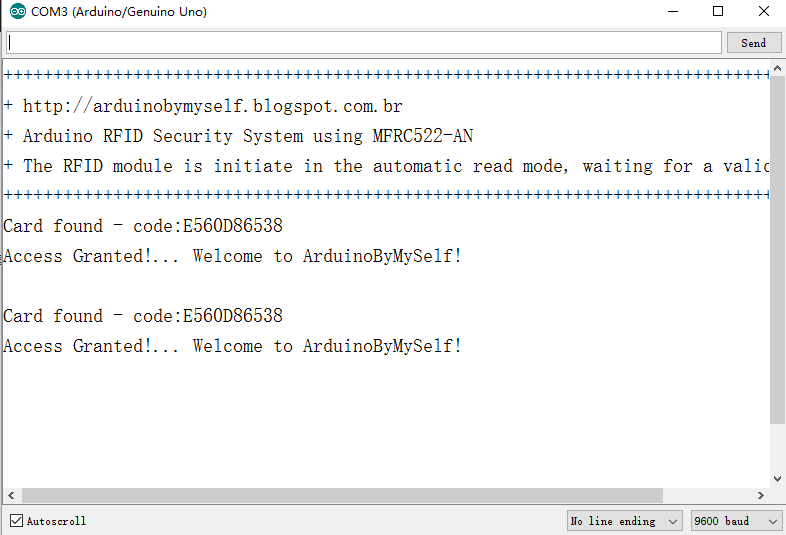
If Key ID does not match record, then RED LED will turn on, LCD shows “Card not recognized! contact admin”. In serial window(upright corner of Arduino IDE), you will see following information: “Card found – code: ** ** ** ** ** ” , ‘** ** ** ** **’ is 5-byte Hex ID of your key.
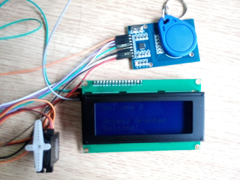
If the ID matches our record(security passed), make servo motor turn 180 degree(imitating door opening) and turn on the green LED and LCD screen show “ID Found!… Welcome X!”.
If the key Hex ID codes matches the any of the Hex ID array of user A,B,C (defined in line 25,26 27 in file RFID_Simples_V3_English.ino), system will consider the key is authorized ID card. So you can change the line 25, 26, 27 and make user A/B/C match your real key code( get from serial window) to test scenario of authorized Key situation.
2 . Devices used in this project
OSOYOO Basic board x 1 ;
Servo Motor x 1;
RFID key and receiver;
Buzzer x 1
220 ohm resistor x 2;
Red LED x 1;
Green LED x 1;
I2C LCD x 1;
Breadboard and jumper wires;
3) Circuit Connection:
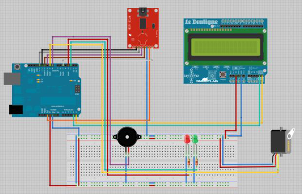
OSOYOO Basic board/RFID sensor pin connection:
| RFID sensor |
OSOYOO Basic board |
| Reset |
D5 |
| SDA |
D10 |
| MOSI |
D11 |
| MISO |
D12 |
| SCK |
D13 |
| GND |
GROUND |
| 3.3v |
3.3v |
OSOYOO Basic board/LCD(i2c) pin connection:
| I2C LCD |
OSOYOO Basic board |
| SDA |
A4 |
| SCL |
A5 |
| VCC |
5V |
| GND |
GND |
OSOYOO Basic board/LED and Servo connection:
| device |
OSOYOO Basic board |
| Red LED long leg |
D3 |
| Green LED long leg |
D2 |
| servo signal(orange line) |
D9 |
| servo VCC(red line) |
5v |
| servo GND(brown line) |
GND |
| Buzz VCC |
D8 |
4)Software installation
Download Arduino Library code and library from following link https://osoyoo.com/driver/RFID.rar
Unzip above file and you will see a folder called RFID, enter into this folder, you will see a sub-folder “library”, this folder has libraries required by this project. Copy all these 5 folders in library into your IDE library folder(normally it should be in Arduino\library )
5)find the I2C address
Each device has an I2C address that it uses to accept commands or send messages. For Uno board, this address usually is 0x27. But sometimes the address might be changed 0x37,0x24 …., So let’s go and look for the one on your device.
Download ic2_scanner sketch file and load it into Arduino IDE. By opening up the serial monitor in the upright corner, the board will scan the address range looking for a reply. Most board will show 0x27, however it be other number.
Write down the Address that you have found, you’ll need it in the following step.
6)Run the project
Go to RFID/RFID_Simples_V3_English folder and open RFID_Simples_V3_English.ino with your IDE
Set the I2C address to match ic2_scanner output value. Use your I2C address to replacement the following code:

and then load the project
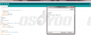
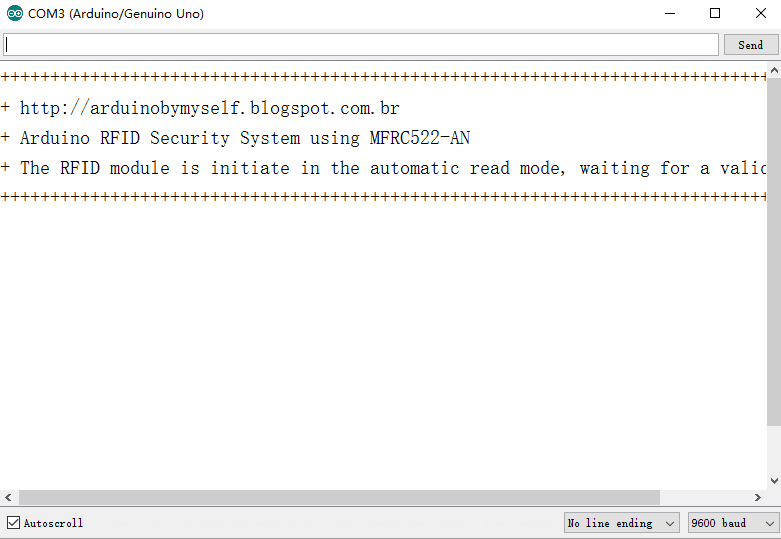
7)In IDE serial window, you will see following info Serial Monitor of your IDE:
Put a RFID key to sensor, you may see:
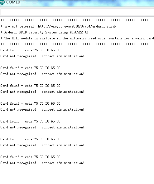
Writer the card code, you’ll need it in the following step.
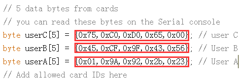
8)Replace the RFID key code in project code to make your rfid key valid(such as the code: 75 C0 D0 65 00, write as 0x75,0xC0,0xD0,0x65,0x00):
9)Once you put a valid RFID key to sensor, you will see Serial Monitor of your IDE:
Servo will turn 180 degree,buzzer will beep and green LED will turn on


Sir good day about this project i want to make it work when the card is still in and card reader when i remove the card the door locks again . how to change the code ?thanks
our sample code actually can meet your requirment.When you tap the key into RFID sensor, the lock(we use servo to immitate lock) will open. After 3 seconds, the lock will automatically close. In our project Arduino file RFID_simples_V3_English.ino line 135 to 137, you can change the parameter in function doorLock.write() to control the lock open or close, you can also change the delay time in line 136.
Hello
can you help me with these
1- How can I change the login sound? I want regular sound not a music
2- I want to change the startup screen “RFID Test by etc”
3- I want to change the user “Welcome A” to “Welcome (any name)”
4- can I add a 4*4 keybad?
last thing
5- I don’t want to close the door automatically I want to scan the opening card to close it can I do that?
1. It can’t change the sound in this code
2. You can change the line 333 to 380 code “RFID_Simples_V3_English”
3. You can try to change the codes about User A
4. You need to change the code and set the graph
5. In our project, When you tap the key into RFID sensor, the lock(we use servo to immitate lock) will open. After 3 seconds, the lock will automatically close. In our project Arduino file RFID_simples_V3_English.ino line 135 to 137, you can change the parameter in function doorLock.write() to control the lock open or close, you can also change the delay time in line 136
thank you very much
I will start fixing that right now and I will give you my upadate
It’s my pleasure.
Hi again
I am trying to add the keypad
but it’s not working
can you help me with the code
I want to open the door(servo) by using the RFID and Password
I connected the keypad as the diagram show and I include the keypad
and library but i got this
Arduino: 1.8.2 (Windows 10), Board: “Arduino/Genuino Uno”
C:\Users\Alienware\Downloads\Compressed\ArduinoRFID\RFID_Simples_V3_English\RFID_Simples_V3_English.ino:19:20: fatal error: Keypad.h: No such file or directory
#include
^
compilation terminated.
Multiple libraries were found for “SPI.h”
Used: C:\Program Files (x86)\Arduino\hardware\arduino\avr\libraries\SPI
Not used: C:\Program Files (x86)\Arduino\libraries\SPI
Multiple libraries were found for “Wire.h”
Used: C:\Program Files (x86)\Arduino\hardware\arduino\avr\libraries\Wire
Not used: C:\Program Files (x86)\Arduino\libraries\Wire
exit status 1
Error compiling for board Arduino/Genuino Uno.
Invalid library found in C:\Program Files (x86)\Arduino\libraries\examples: C:\Program Files (x86)\Arduino\libraries\examples
Invalid library found in C:\Program Files (x86)\Arduino\libraries\examples: C:\Program Files (x86)\Arduino\libraries\examples
This report would have more information with
“Show verbose output during compilation”
option enabled in File -> Preferences.
I’m sorry I don’t test this tutorial with keypad, but you can try the tutorial about keypad: https://osoyoo.com/2016/07/21/4x4keypad/
can I add the keypad code to the code above?
if yes how can I fix keypad code to make it working with the codes above
Please try to compile two part code together and change some code and have a try
Hi, I’ve checked four times that the RFID sensor is wired correctly, but it still isn’t reading the card or tag. How do I troubleshoot that? Thanks
Do you solder the pin on the RFID sensor?
i also have soldered the pins to rfid sensor. good clen joins. no dry joints. still not working. just D1 led on rfid sensor is permantly lit.
Please help. !!
Are you willing to try to the tutorial: https://osoyoo.com/2017/09/11/arduino-lesson-rfid-rc522/?
This tutorial is just for RFID sensor. Please confirm whether the sensor works or not.
Hi. Thanks for the guide but this is soo far from accurate. the picture layout at the top (47.jpg) doesn’t even match and is such a low resolution i cant see the pins..
Is there a more comprehensive guide please? or if anybody has got this to work, can you share a close up pictures please?? and codes too please?
i really want buzzer, leds, lcd servo and rfid to work, but with the pin out and instructions above
i only have D1 led lit.
The little servo is making a very quiet hum sound and resisting being turned.
When rebooting, the lcd comes on and then off after a few seconds
the code is saying it’s waiting for Valid card in the com port monitor window.
PLEASE PLEASE can you share better pictures of the layout of working project. 🙁
Hi, cheers for the tutorial everything is working fine except that nothing is appearing on the LCD Display. It lights up when I hold a card to the RFID reader but for what ever reason no text is appearing. Do I need to add something to the code for the text to appear? If so please advise.
Please adjust the backlight of the LCD.
Do you check the I2C address of your LCD and change I2C address when you run the project?
can replace with lcd 16×2 and MFRC 522