Note: ALL OSOYOO Products for Arduino are Third Party Boards that are fully compatible with Arduino.
Authorized Online Retailers:
Content
-
- What is Arduino?
- Why choose Arduino?
- Types of Arduino
- What Is Inside an Arduino / What’s on the board?
- What is the Arduino IDE?
What is Arduino?
Arduino is an open-source electronics prototyping platform designed for engineers, hobbyists, designers, and anyone interested in creating interactive electronics projects. It is a flexible platform based on easy-to-use software and hardware. Arduino combines a microcontroller with an Integrated Development Environment (IDE) that runs on laptops or computers, making it simple to write and upload programs to the physical board.
Arduino boards can read inputs — light, proximity, or air quality from a sensor, or a message from the internet — and turn them into outputs: activating a motor, turning on a light, or triggering external events. You tell your board what to do by writing code and uploading it to the microcontroller using the Arduino programming language (based on Wiring) and the Arduino Software (IDE), which is based on Processing.
Over the years, Arduino has powered thousands of projects and brought together a worldwide community where beginners and experts share ideas, knowledge, and experience. Makers, students, artists, designers, programmers, researchers, professionals, and hobbyists all over the world use Arduino for learning, prototyping, and finished professional work.
Arduino was born at the Interaction Design Institute Ivrea (IDII) from the Wiring project as a simple tool for fast prototyping, aimed at students without a background in electronics or programming. The goal was to make working with technology and electronics easier for everyone. The Arduino board has evolved from simple 8-bit boards to products ready for IoT applications. All Arduino boards are completely open-source, so users can build them independently and adapt them to their own needs. The software is also open-source and continues to grow through contributions from developers and the Arduino community worldwide.
Many similar projects have been tried, but none have succeeded as well as Arduino — thanks to how easy the software is to use and how affordable the hardware is. The Arduino software is easy-to-use for beginners yet flexible enough for advanced users. It runs on Mac, Windows, and Linux.
Why choose Arduino?
There are many microcontrollers on the market today, so why choose Arduino? Here are some good reasons:
- Unlike other programmable circuit boards, Arduino does not require separate hardware or a programmer to load code onto the board — just a USB cable.
- The Arduino IDE uses a simplified form of C++, making it straightforward to learn programming.
- Arduino supports a standard form factor.
- No previous electronics experience is required.
- Arduino offers a great platform for hobbyists to bring their project ideas to life.
- Inexpensive compared to similar boards.
- Simpler to use than most competing platforms.
- It is an open-source platform — anyone can modify and build their own Arduino-compatible board.
- Arduino is based on Atmel’s ATmega168 and ATmega8 microcontrollers.
- Advanced users can easily extend and improve the Arduino board for their own projects.
Types of Arduino
Arduino has many board variants, starting from the basic Arduino UNO and ranging up to the Arduino Mega, Arduino Fio, LilyPad, and many more.
What Is Inside an Arduino / What’s on the board?
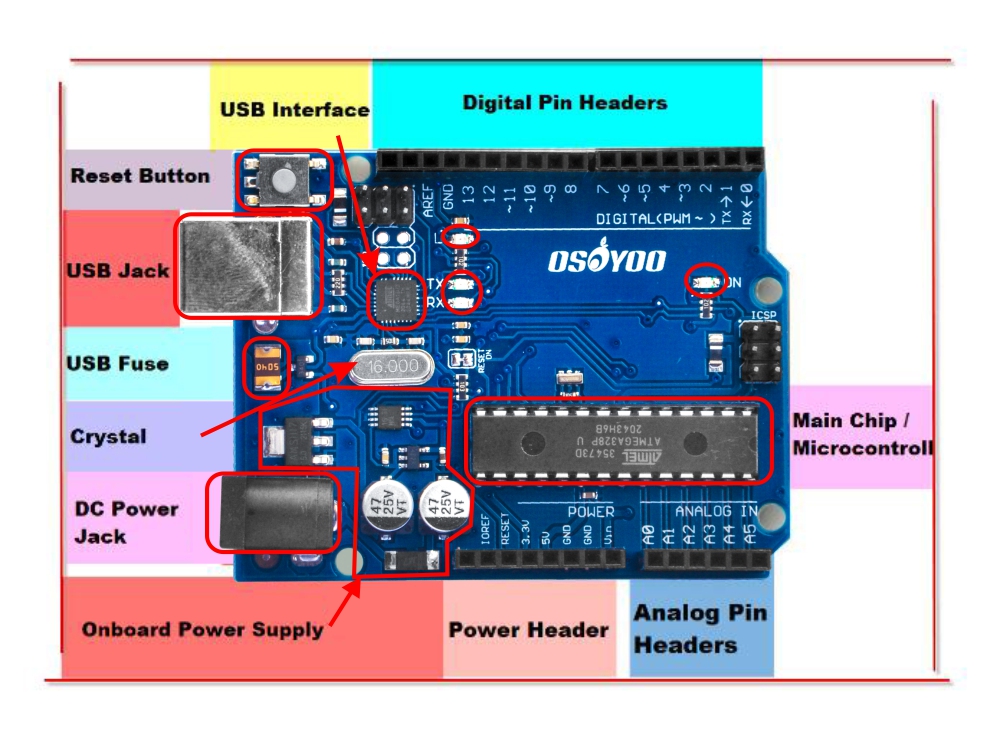
Don't feel like you have to understand this part fully! Skim it for now,
and come back to it when you want to take a deeper dive
into understanding the hardware.
Main Chip / Microcontroller
The black component with all the metal legs is an IC (Integrated Circuit) (13). Think of it as the brain of the Arduino. The main IC varies slightly between board types, but it is usually from the ATmega line of chips made by ATMEL. This matters because you may need to know the IC type (along with your board type) before loading a new program from the Arduino software. This information is usually printed on the top of the IC. If you want to learn more about the differences between ICs, reading the datasheets is a good place to start.
Power (USB / Barrel Jack)
Every Arduino board needs a power source. The Arduino UNO can be powered from a USB cable connected to your computer, or from a wall power supply with a barrel jack connector.
The USB connection is also how you load code onto your Arduino board. More on programming with Arduino can be found in our Installing and Programming Arduino tutorial.
NOTE: Do NOT use a power supply greater than 20 V, as you will overpower (and likely destroy) your Arduino. The recommended voltage for most Arduino models is between 6 and 12 V.
Onboard Power Supply
The Arduino is designed with beginners in mind and includes protection and regulation circuitry so it can work with a wide range of power supplies. In particular, there is a polarity protection diode (to protect the board if you accidentally connect a Negative Tip adapter). It also has an onboard 5 V voltage regulator.
USB Jack & Interface
USB Jack
This is how you connect your Arduino to your computer. Any computer with a USB port will work. You will need a USB cable — this cable is usually included in the OSOYOO kit.
USB Interface Chip
When you plug your Arduino into a computer, you might be surprised to learn that the main processor chip (ATmega328) cannot communicate over USB directly. Instead, it uses a simpler protocol called “Serial.” So how does a chip that speaks Serial connect to a USB port? With a USB-to-Serial Interface Translator chip. Just like a human interpreter, it speaks both languages and seamlessly translates between them.
There are many different translator chips in use. Common part numbers include FTDI FT232, FTDI FT231X, CP2102 or CP2104, PL2303, and CH340, among others. They are all nearly identical, but some require different operating system drivers.
Arduino LEDs
The Arduino has four LEDs: L, RX, TX, and ON.
ON LED
This LED glows green whenever the Arduino is powered. If it is flickering or off, check your power supply.
RX and TX LEDs
These work like the send and receive indicators on a cable modem. They blink whenever information is sent to or from the Arduino through the USB connection.
The TX LED lights up yellow whenever data is sent from the Arduino to the computer via USB.
The RX LED lights up yellow whenever data is sent to the Arduino from the computer via USB.
L LED
This is the one LED you can control directly in your code. The ON, RX, and TX LEDs light up automatically. The L LED is connected to the Arduino main chip and you can turn it on or off in your sketch.
For future reference, L is connected to Digital Pin #13.
Power Header
- Vin — Connected to the DC Jack power input, so it carries 7–12 VDC depending on what is plugged in. If the DC Jack is unpowered, it provides the 5 V from the USB connection.
- GND — There are two GND pins here; both are the common ground connection for all power and data.
- 5V — The clean, regulated 5 V supply the Arduino runs on, from the DC jack or USB. Provides up to about 500 mA.
- 3.3V — A clean, regulated 3.3 V supply, needed by some sensors. Provides up to about 100 mA.
- Reset — The same pin connected to the reset button.
- IOref — Used by shields to identify the IO voltage level. You can ignore this pin for now.
- Unnamed pin — Reserved for future use. Do not connect anything to it.
Digital Pin Headers
The two pins labeled 0 (RX) and 1 (TX) are the Serial pins used to send data between the Arduino and the USB-Serial translator chip.
Do not connect anything to Digital 0 or 1 unless you are certain — it will affect your Arduino’s ability to communicate!
- Digital 2 through Digital 12 are standard digital I/O pins.
- PWM Pins: Pins marked with a ~ symbol — 3, 5, 6, 9, 10, and 11 on the UNO — are normal digital pins that can also be used for Pulse-Width Modulation (PWM).
- Digital 13 is special because it is also connected to the L LED. You can use this pin normally, but the L LED will blink at the same time.
A few additional pins:
- A spare power GND Ground pin.
- AREF — Analog Reference pin. Used for advanced analog sensor readings (you will learn about this later).
- Two unlabeled pins (labeled on the bottom of the board). These are the SDA and SCL pins for connecting I2C sensors. They are connected internally to A4 and A5. We do not recommend using these unless you have an I2C sensor.
Analog Pin Headers
Those 6 analog input pins can also be used as digital input/output pins — they are the most versatile pins on the board!
Each analog pin can read a voltage between 0 and 5 V (the same voltage used to power the Arduino).
Once you develop more advanced analog skills, you can connect the ARef pin to a different voltage (such as 3.3 V) to get more precision from your analog readings. We will cover that in a future lesson.
Do not connect a voltage higher than 5 V to the analog input pins — you could damage them!
USB Fuse
The USB fuse protects your Arduino and computer. Since you will be connecting all sorts of wires, there is a chance of accidentally shorting the power. This resettable fuse acts like the circuit breakers in your home — it trips when there is too much current, then resets automatically.
Reset Button
The Arduino has a reset button (10). Pressing it temporarily connects the reset pin to ground and restarts any code loaded on the Arduino. This is handy when your code runs once and you want to test it again.
Pins (5V, 3.3V, GND, Analog, Digital, PWM, AREF)
The pins on your Arduino are where you connect wires to build a circuit (typically using a breadboard and some wire). They usually have black plastic headers that let you plug a wire straight into the board. The Arduino has several types of pins, each labeled on the board.
- GND (3): Short for Ground. There are several GND pins on the Arduino; any of them can be used to ground your circuit.
- 5V (4) & 3.3V (5): The 5V pin supplies 5 volts of power, and the 3.3V pin supplies 3.3 volts. Most simple components used with the Arduino run on 5 V or 3.3 V.
- Analog (6): The pins under the “Analog In” label (A0 through A5 on the UNO) are Analog In pins. They can read signals from analog sensors (like a temperature sensor) and convert them into digital values.
- Digital (7): The digital pins (0 through 13 on the UNO) can be used for both digital input (detecting if a button is pressed) and digital output (powering an LED).
- PWM (8): Pins with a tilde (~) next to them — 3, 5, 6, 9, 10, and 11 on the UNO — act as normal digital pins but can also perform Pulse-Width Modulation (PWM). See our PWM tutorial for more details.
- AREF (9): Stands for Analog Reference. Usually left alone, but it can be used to set an external reference voltage (0–5 V) as the upper limit for the analog input pins.
What is the Arduino IDE?
Arduino provides an open-source, easy-to-use programming tool for writing code and uploading it to your board — the Arduino IDE (Integrated Development Environment). The Arduino Software (IDE) is easy-to-use for beginners, yet flexible enough for advanced users.