


Authorized Online Retailers:
Purchase from US Purchase from Japan


Introduction
In this lesson, we will show how to use the Osoyoo Yun IoT Kit with the Blynk APP to control the RGB module.
Preparations
HARDWARE
- Arduino(Osoyoo Mega2560 here) x 1
- Dragino Yun Shield x 1
- Breadboard x 1
- RGB Module x 1
- Jumpers
SOFTWARE
Connection
Build the circuit as below:
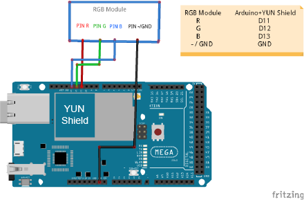
Here we connect the RGB Pin R to D11, Pin G to D12,Pin B to D13,GND to GND.
Code Program
After above operations are completed, make sure that the Yun Shield is on the same network with the computer. Open the Arduino IDE and choose corresponding board type and port type for you project. Then load up the following sketch onto your Arduino.
#define BLYNK_PRINT Console
#include “Bridge.h”
#include “Console.h”
#include “BlynkSimpleYun.h”
// You should get Auth Token in the Blynk App.
// Go to the Project Settings (nut icon).
char auth[] = “YourAuthToken”;
void setup()
{
// Debug console
Console.begin();
Blynk.begin(auth);
while (!Console);{}
// You can also specify server:
//Blynk.begin(auth, “blynk-cloud.com”, 8442);
//Blynk.begin(auth, IPAddress(192,168,1,100), 8442);
}
void loop()
{
Blynk.run();
// You can inject your own code or combine it with other sketches.
// Check other examples on how to communicate with Blynk. Remember
// to avoid delay() function!
}
In this example sketch, find this line:
char auth[] =”YourAuthToken”;
This is the Auth Token that you emailed yourself. Please check your email and copy it, then paste it inside the quotation marks.
It should look similar to this:
char auth[] = “f45626c103a94983b469637978b0c78a”;
Upload the sketch to the board. Wait until you see something like this:
avrdude done. Thank you.
Congrats! You are all set! Now your hardware is connected to the Blynk Cloud!
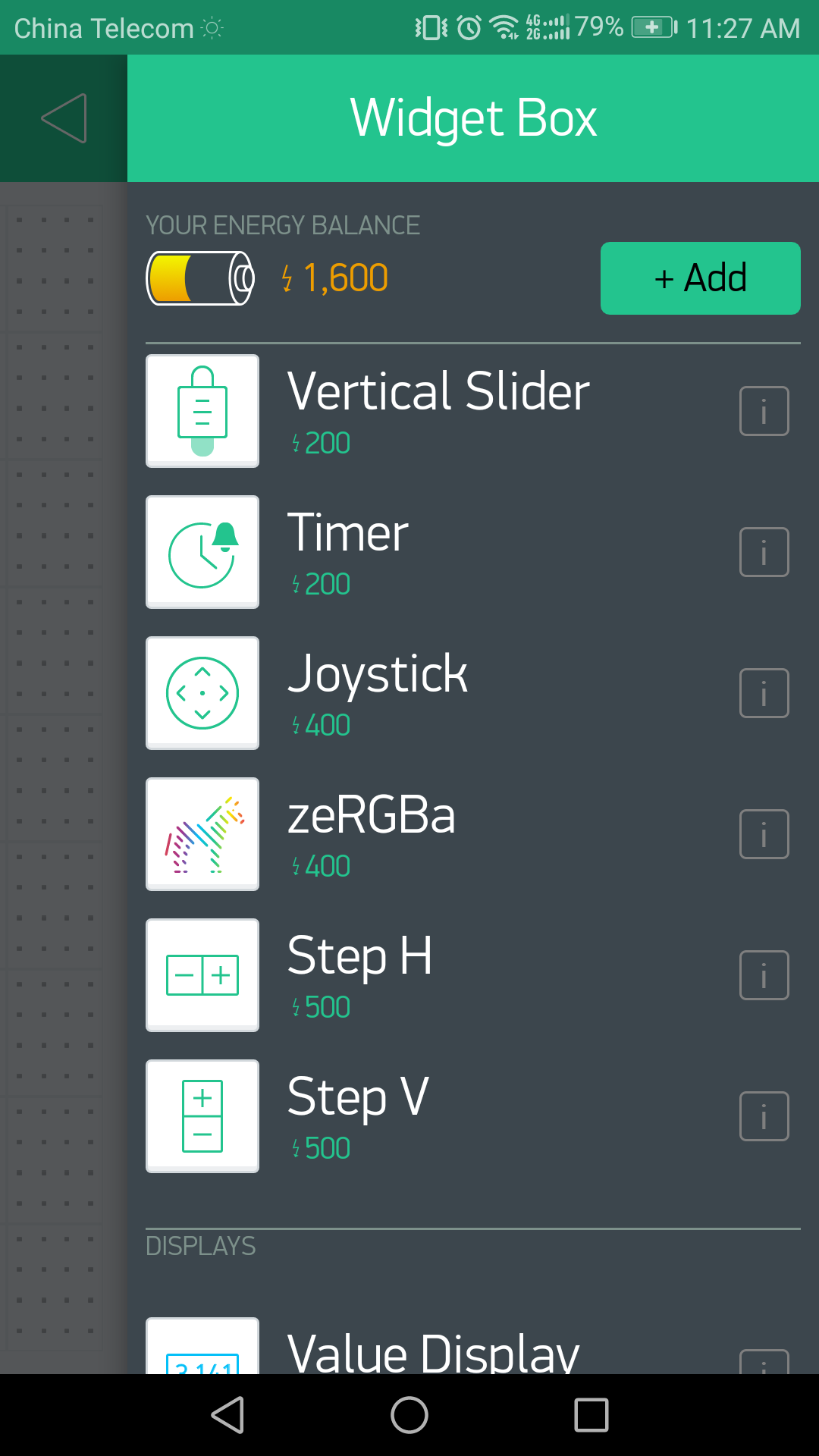
Add a Widget
Your project canvas is empty, let’s add a zeRGBa to control our RGB module.
Tap anywhere on the canvas to open the widget box. All the available widgets are located here. Now pick a zeRGBa.
Widget Box
Drag-n-Drop – Tap and hold the Widget to drag it to the new position.
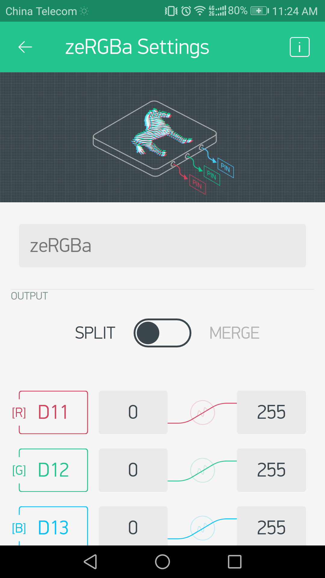
Widget Settings – Each Widget has it’s own settings. Tap on the widget to get to them.
The most important parameter to set is PIN . The list of pins reflects physical pins defined by your hardware. Here we connect the RGB Pin R to D11, Pin G to D12,Pin B to D13. (D – stands for Digital).
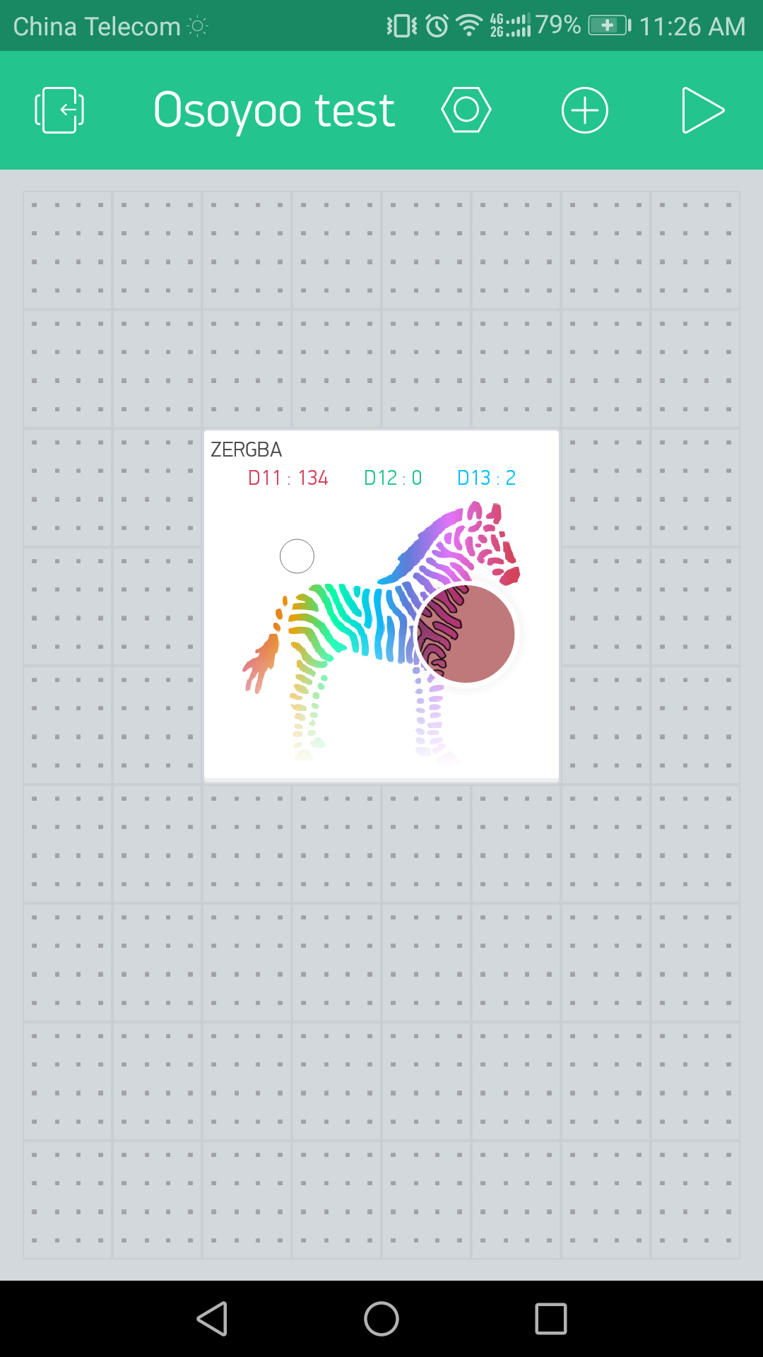
Running Result
After you finished all above operations, open the Serial Monitor, then open the Blynk APP, press the PLAY button. This will switch you from EDIT mode to PLAY mode where you can interact with the hardware. While in PLAY mode, you won’t be able to drag or set up new widgets, press STOP and get back to EDIT mode.
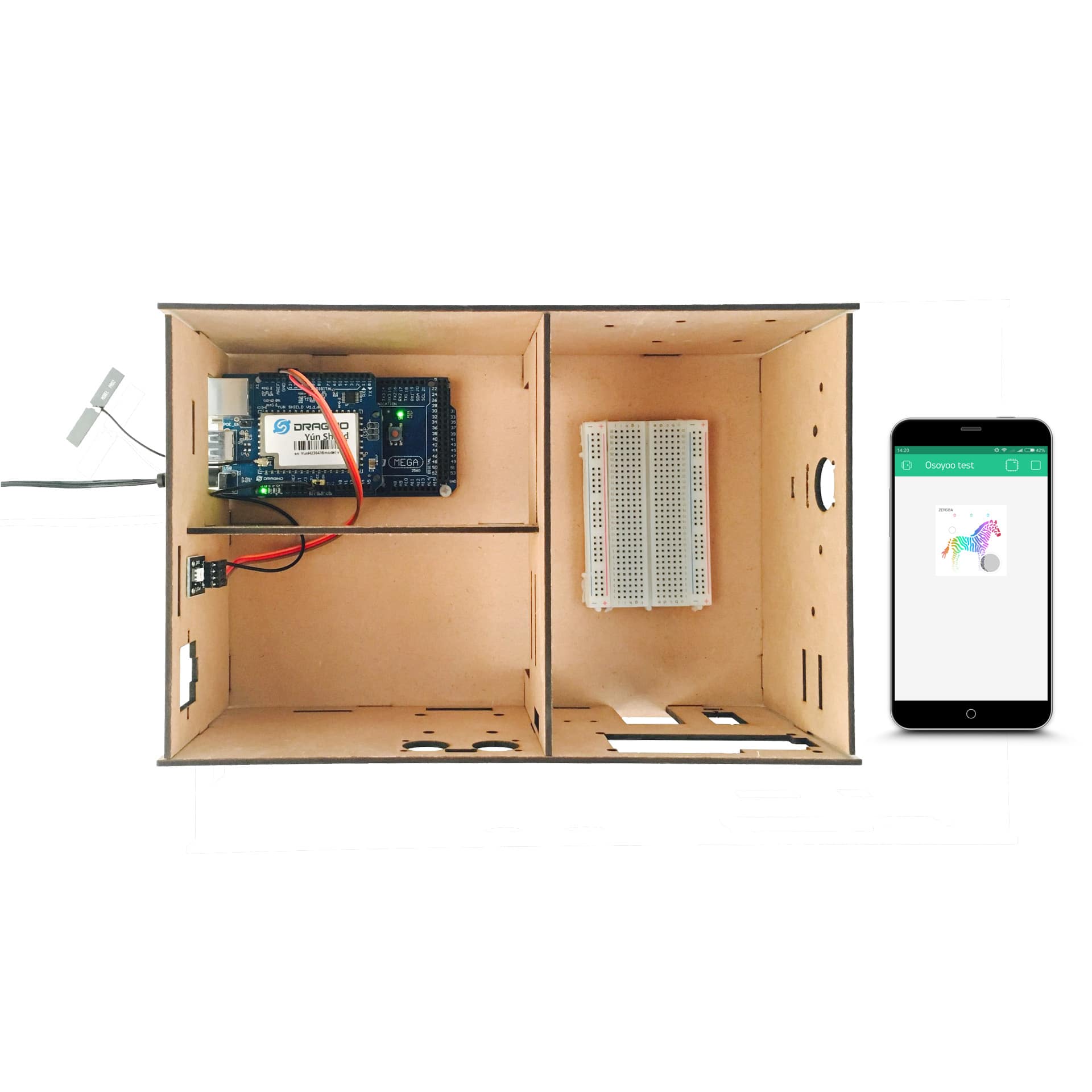
At the same time, you can see the hardware side as below:
So, you just have completed the RGB remote control experiment.


