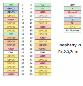
Raspberry Pi i/p pins are located in the upper left corner of board, see following picture:

These pins are combination of Voltage supplies, Grounds and GPIO (general purpose input/output) pins. You can distinguish them from following graph:

Understand those pins functions are fundamental to design projects which allow Raspberry Pi to communicate with sensors and many other devices.
Detail explanation of pins:

-
GPIO are your standard pins that simply be used to turn devices on and off. For example, a LED.
-
I2C (Inter-Integrated Circuit) pins allow you to connect and talk to hardware modules that support this protocol (I2C Protocol). This will typically take up 2 pins.
-
SPI (Serial Peripheral Interface Bus) pins can be used to connect and talk to SPI devices. Pretty much the same as I2C but makes use of a different protocol.
-
UART (Universal asynchronous receiver/transmitter) are the serial pins used to communicate with other devices.
-
DNC stands for do not connect, this is pretty self-explanatory.
-
The power pins pull power directly from the Raspberry Pi.
-
GND are the pins you use to ground your devices. It doesn’t matter which pin you use as they are all connected to the same line.
if you want to write code to test GPIO code, check our tutorial Use LED to test GPIO pin


