Objective:
In this project, we will use raspberry Pi to drive buzzer and make alert sound repeatedly.
Parts and Devices
1 x raspberry Pi3
1 x raspberry Pi T-style extension
1 x buzzer
mouse and keyboard
HDMI cable and HDMI monitor(or LCD TV)
1 x breadboard
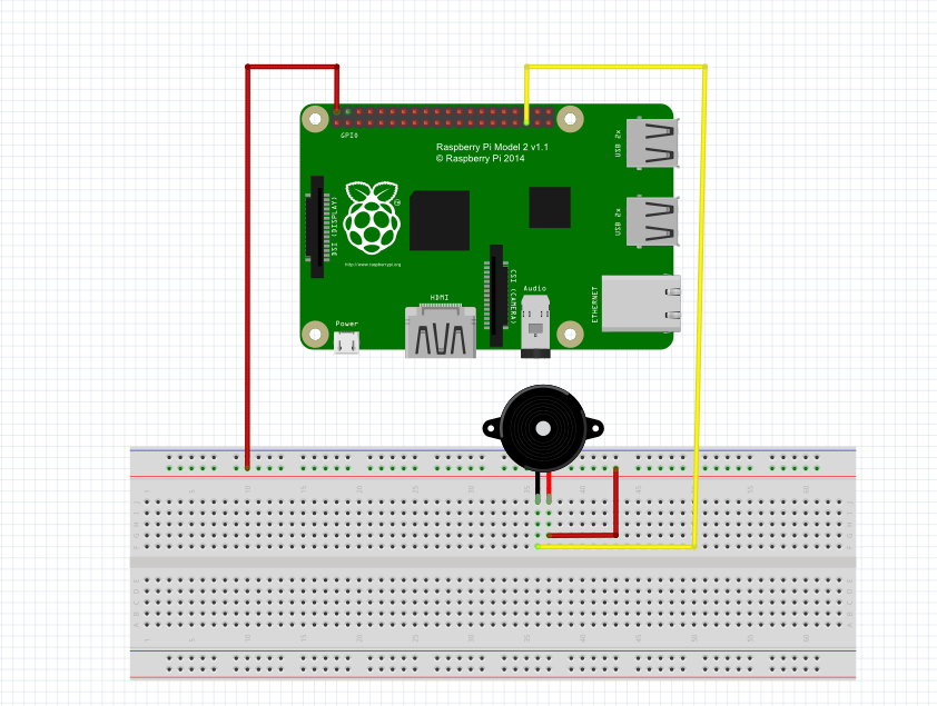
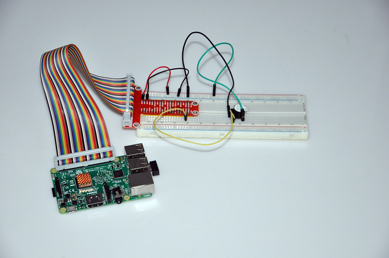
Circuit Graph:

Software Installation:
1)Install git core(if you have already installed git core, please skip this step). Please run following shell command in Pi terminal:
sudo apt-get install git-core
sudo apt-get update
sudo apt-get upgrade
2)Install wiringPi libary(if you have installed wiringPi, please skip this step). Please run following command in Pi terminal:
git clone git://git.drogon.net/wiringPi
cd wiringPi
./build
3)Download/compile buzzer_rpi.c and run the program as following:
wget http://osoyoo.com/wp-content/uploads/2016/09/buzzer_rpi.c
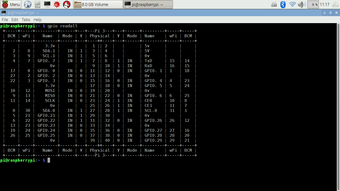
Note: In buzzer_rpi.c file, the buzzer is connected to port no.24. However, connection graph shows the buzzer is connected to GPIO 19. This is because buzzer_rpi.c includes wiringPi library whose port number does not match GPIO number. port 24 is actually GPIO 19. You can use gpio readall to check gpio port mapping(result as per following graph)

compile and run the code by typing following commands:
gcc -Wall -o buzzer buzzer_rpi.c -lwiringPi
sudo ./buzzer
you will hear buzzer sound.

use “Ctrl+c “ to stop the program


Project calls for a PNP Transistor, but no transistor was included in the raspberry pi starter learner kit. 🙁
サンプルの回路図は、Raspberry Piの5Vをブザーの+、Raspberry PiのGPIO19をブザーの-に接続しているようです。
プログラムではGPIO19はOUTPUTに接続しているようなので問題ある気がしますがいかがでしょうか?
Raspberry PiのGPIO19をブザーの+に接続。Raspberry PiのGNDをブザーのGNDに接続すればよいと思いますが。。。。
お問い合わせ、ありがとうございます。
ラズパイからブザーへ信号を転送して、ブザーを発声のテストです。
ブザーからデータを獲得しませんので、プログラムでのoutputは問題ありません。ご了承くださいませ。
「Raspberry PiのGPIO19をブザーの+に接続。Raspberry PiのGNDをブザーのGNDに接続すればよい」そうしても大丈夫だと思いますが、ラズパイからブザーに高電位信号を発信の必要です、もしラズパイの給電が不足の場合、高電位信号の電圧値が足りないため、ブザーが上手く作動できなくなると思います。
どうぞよろしくお願い致します。