In this project, we will use I2C LCD working as a monitor. We can use PC serial port to send text message from PC to I2C LCD and get response from Arduino.
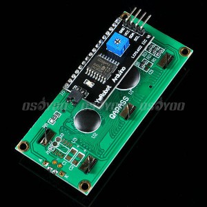

Osoyoo I2C 1602 LCD based on the 1602 panel with a small back-panel to convert it to I2C. The old style 1602 LCD needs 4 data lines + 2 control lines and totally occupies 6 digital ports. The new Osoyoo I2C LCD occupies only two analog ports and saves lots of Arduino port resources.
Setup instructions :
Step 1: Download LiquidCrystal_I2C.zip library file and Install I2C library:
This library REPLACES the standard one in Arduino V1.0. So
– in Arduino root fold->libraries rename the existing LiquidCrystal library directory
– unzip the LiquidCrystal_I2C.zip file
– place the folder LiquidCrystal_I2C into the libraries folder.
– in Arduino IDE click: Sketch->Import Library ->Add Library , then select above LiquidCrystal_I2C fold and open.
the import library list should show a new item “LiquidCrystal_I2C”
– Start up the Arduino IDE
Step 2 – Connect LCD with OSOYOO basic board for Arduino
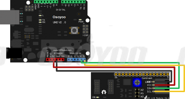
For Uno R3 , the I2C connections are on SDA=A4 and SCL=A5. So go ahead and wire these up, along with the two power leads to the 5V and GND terminals.

For Mega2560 , the I2C connections are on SDA=20 and SCL=21. So go ahead and wire these up, along with the two power leads to the 5V and GND terminals.
Step 3 – Power up your devices.
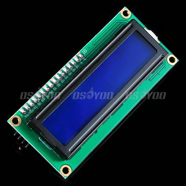
You should see the LCD light up. Depending on how the device was constructed, you might want to turn down the contrast of the LCD; you can do this by inserting a screwdriver into the potentiometer at the back. I suggest you turn it half-way so that there’s still a little contrast.
Step 4 – find the I2C address
Each device has an I2C address that it uses to accept commands or send messages. For Uno board, this address usually is 0x27. But sometimes the address might be changed 0x37,0x24 …., So let’s go and look for the one on your device.
Download ic2_scanner sketch file and load it into Arduino IDE. By opening up the serial monitor in the upright corner, the board will scan the address range looking for a reply. Most board will show 0x27, however it be other number.
Write down the Address that you have found, you’ll need it in the next step.
Step 5 – Fire up the LCD
Download Serial to I2C LCD test sketch file and set the I2C address to match ic2_scanner output value, load it into Arduino IDE.
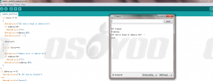
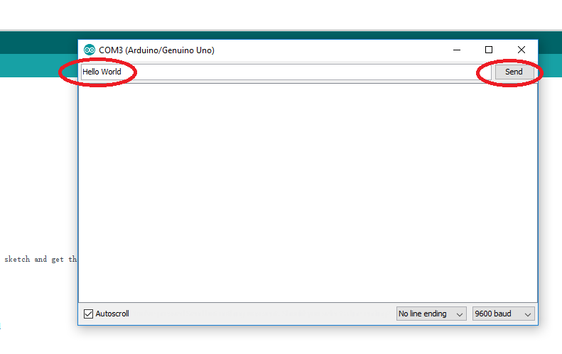
Open the Arduino IDE serial window type “Hello World” in terminal as following:

You will see I2C LCD shows “hello world” and serial window shows “Hello world displayed”


I’ve followed your instructions but the ic2_scanner sketch returns “No I2C devices found”. The device powers up. I’ve double checked the wiring. All the components are from the Osoyoo starter kit.
In my version of the Arduino IDE (1.8.2), they don’t have: Sketch->Import Library so I manually copied the library file to the Arduino Library folder and the library shows up under “contributed libraries”. Your sketches compile and run without error.
Any suggestions?
Thank you.
Are you willing to take a photo about the wiring and send to my email address: [email protected]